Flying saucer type LED lamp assembly

An LED lamp assembly and LED lamp panel technology, applied in the field of flying saucer LED lamps, can solve the problems of shortened service life of the LED lamp panel, erosion and damage of the LED lamp panel circuit, difficulty in replacing the LED lamp panel, etc., and achieves a beautiful and good overall structure. Waterproof, easy-to-separate effect

Pending Publication Date: 2017-05-31
江门市光动力能源科技有限公司
View PDF6 Cites 2 Cited by
  • Summary
  • Abstract
  • Description
  • Claims
  • Application Information

AI Technical Summary

Problems solved by technology

The existing flying saucer-type LED lamp driving components are all fixed on the lamp holder by screws. Since the installation seat needs to be prefabricated on the lamp holder, and the lamp holder is generally made of metal products, the production is more troublesome; And dust erosion, small mosquitoes will also enter, moisture, dust and mosquitoes will be adsorbed on the LED lamp panel, which will cause the circuit of the LED lamp panel to be eroded and damaged, thereby shortening the service life of the LED lamp panel. The existing waterproof and dustproof 1. The connection structure between the lampshade and the lamp holder in the anti-mosquito flying saucer LED lamp is either very complicated, difficult to disassemble, difficult to replace the LED lamp panel, or glued, the lampshade is easy to fall off after aging

Method used


Image

  • Flying saucer type LED lamp assembly
  • Flying saucer type LED lamp assembly
  • Flying saucer type LED lamp assembly

Examples


Embodiment Construction

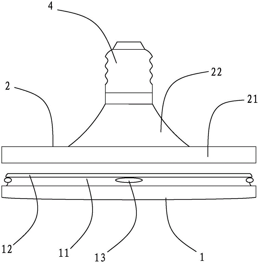
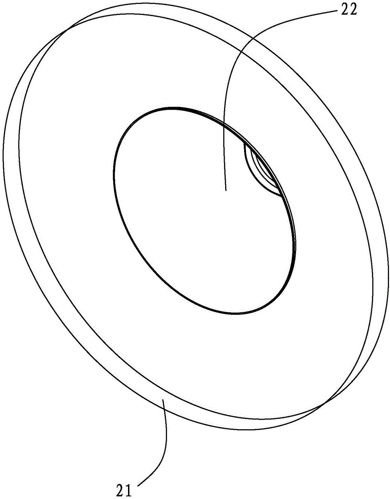
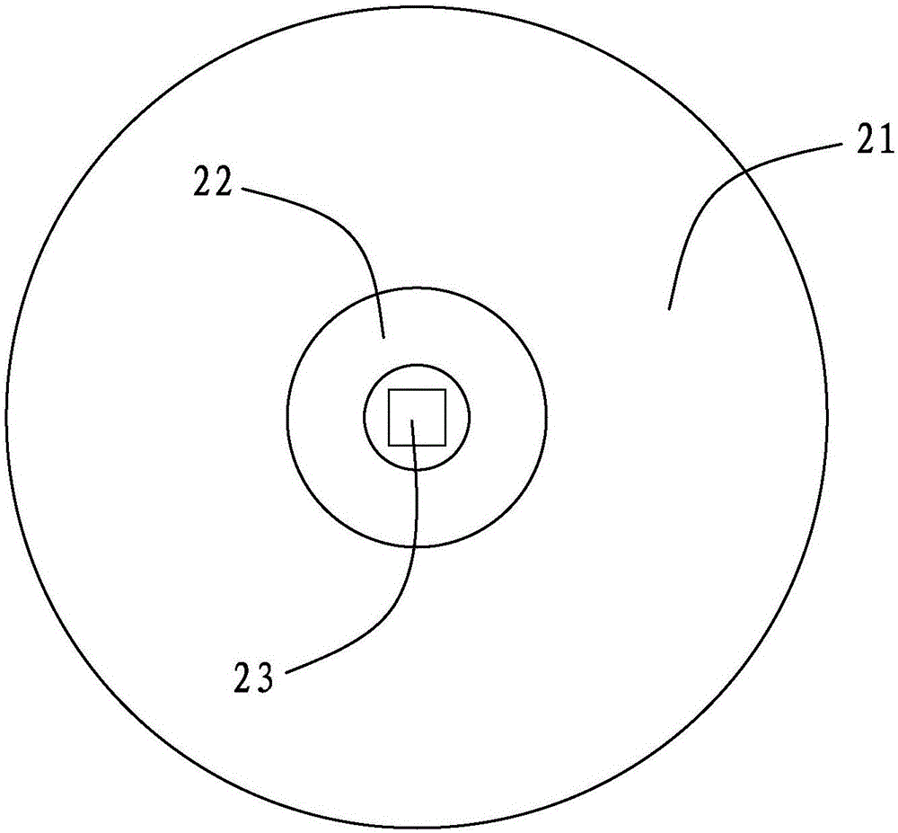
[0019] refer to Figures 1 to 2 , a flying saucer type LED lamp assembly, including a lampshade 1, a lamp holder 2, an LED lamp panel 3, a drive assembly and a connector 4, the lampshade 1 and the connector 4 are arranged on the upper and lower sides of the lamp holder 2, and the lamp holder 2 includes a circle The disc-shaped housing 21 is provided with inner curling on the lower edge of the circumference of the housing 21, and the entire lamp holder 2 is formed by pressing a thin plate. The upper side of the lampshade 1 is provided with a flange 11 adapted to the inner ring of the housing 21. The upper edge of the flange 11 extends outward from the outer collar 12. The lampshade 1 and the lamp holder 2 pass through the gap between the flange 11 and the housing 21. The fit and the fit between the outer collar 12 and the inner curling are fixed, and the flange 11 on the lower side of the outer collar 12 is provided with four smooth protrusions 13 along the circumference, and t...


PUM


Abstract

The invention discloses a flying saucer type LED lamp assembly which comprises a lampshade, a lampholder, an LED lamp panel, a driving assembly and a connector, wherein the LED lamp panel is arranged in the lampshade; a plurality of LED lamp beads are arranged on the lower side face of the LED lamp panel in a circumference layer-by-layer distribution manner along the center; the driving assembly comprises a circuit board, and electric components are welded on the circuit board; the bottom surface of the circuit board is welded in the center of the upper side of the lamp panel through a solid adhesive tape; the lampshade and the connector are arranged on the upper and lower sides of the lampholder; the lampholder comprises a disciform shell; a flange matched with the shell is arranged on the upper side of the lampshade; an inner hemming is arranged on the lower edge of the circumference of the shell; the upper edge of the flange extends outwards out of an outer clamping ring; the lampshade and the lampholder are fixed through interference fit of the flange and the shell and through matching of the outer clamping ring and the inner hemming; a plurality of smooth lug bosses are arranged on the flange on the lower side of the outer clamping ring in the circumferential direction; the connector comprises a thread lamp cap and a fixed head; the thread lamp cap is arranged in the center of top of the lampholder; the fixed head is arranged in the center of the inner side of the lampholder; and the thread lamp cap and the fixed head are in threaded connection.

Description

technical field [0001] The invention relates to an LED lamp, in particular to a flying saucer type LED lamp. Background technique [0002] Since the development of LED lamps, various products have been derived, which are becoming more and more popular. UFO-style LED lamps are one of the most widely used. The existing flying saucer-type LED lamp driving components are all fixed on the lamp holder by screws. Since the installation seat needs to be prefabricated on the lamp holder, and the lamp holder is generally made of metal products, the production is more troublesome; And dust erosion, small mosquitoes will also enter, moisture, dust and mosquitoes will be adsorbed on the LED lamp panel, which will cause the circuit of the LED lamp panel to be eroded and damaged, thereby shortening the service life of the LED lamp panel. The existing waterproof and dustproof 1. The connection structure between the lampshade and the lamp holder in the mosquito-proof flying saucer LED lamp ...

Claims


Application Information

Patent Timeline
IPC IPC(8): F21K9/23F21K9/238F21V23/00F21V17/10F21V31/00F21Y115/10F21Y105/18
CPCF21V17/10F21V23/003F21V31/005
Inventor 杨兴中
Owner 江门市光动力能源科技有限公司
Why Eureka
Try Eureka