Six-layer-wall-thickness strengthened type radiating pipe
A heat dissipation pipe and enhanced technology, applied in the field of heat dissipation pipes, can solve the problems of low system pressure and low structural strength, and achieve the effects of increasing pressure bearing strength, improving corrosion resistance, and facilitating cleaning
- Summary
- Abstract
- Description
- Claims
- Application Information
AI Technical Summary
Problems solved by technology
Method used
Image

Examples
Embodiment 1
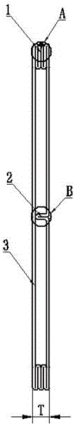
[0020] Such as figure 1 Shown is a six-layer thickened heat dissipation pipe, five consecutive bends 1 are arranged between the two ends of the two opposite side walls of the heat dissipation pipe, and the adjacent bent edges are closely bonded.
[0021] There is a long inner bend 2 sunken inward on one side of the heat pipe wall 3, the top of the long inner bend 2 is in close contact with the other side of the tube wall 3, and the two bent sides of the long inner bend 2 are also in close contact ,. From the cross-sectional shape, one side of the heat pipe is a straight line, the middle part of the other side is concave inward, and the side pipe wall is concave inward to form a long inner bend 2 with a double-layer composite structure in contact with the two sides. The long inner bend 2 will The interior of the heat dissipation pipe is spaced into two independent pipe holes.
[0022] The heat dissipation pipe is made of aluminum foil material after forming and high-frequency...
Embodiment 2
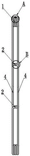
[0024] The difference between this embodiment and the first embodiment is that the tube walls 4 on both sides of the heat pipe are respectively provided with a long inner bend 2 sunken inward, and the top of the long inner bend 2 is in close contact with the tube wall 4 on the other side. Seen from the cross-sectional shape, one side of the heat pipe has an inward depression, the other side has an inward depression, and there are two inward depressions on both sides. The two long inner bends 2 of the tube walls 4 on both sides space the inside of the heat dissipation pipe into three independent tube holes, and the upper and lower sides of the long inner bends 2 are close together to form surface contact.
Embodiment 3
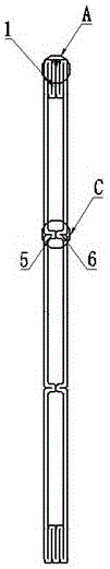
[0026] The difference between this embodiment and Embodiment 1 is that two short inner bends are provided on both sides of the heat pipe respectively, and the bending edges of each short inner bend are closely attached to each other. The top ends of the two short inner bends 5 on the tube wall are opposite to and in close contact with the top ends of the two short inner bends 6 on the other side of the tube wall, and as Image 6 As shown, the top bending edge 8 of the short inner bend 5 and the top bending edge 9 of the short inner bend 6 are close together to form a surface contact to form a double-layer composite structure, and the relative short inner bends 5 and 6 will dissipate heat The interior of the tube is divided into three independent tube holes.
PUM
| Property | Measurement | Unit |
|---|---|---|
| Thickness | aaaaa | aaaaa |
| Wall thickness | aaaaa | aaaaa |
Abstract
Description
Claims
Application Information
PatSnap Eureka turns technology decisions into work you can execute. Powered by our Innovation Knowledge Graph, it runs expert workflows across engineering, life sciences, materials and intellectual property. Get your review-ready output in minutes.


