Guide rail basal plane straightness error decoupling and identifying method

A technology of straightness error and identification method, which is applied in the direction of instruments, measuring devices, optical devices, etc., can solve the problems of difficult accurate measurement and acquisition of the straightness error of the base surface of the guide rail, and achieve the effect of accuracy and feasibility

Active Publication Date: 2017-05-31
HUAZHONG UNIV OF SCI & TECH
View PDF7 Cites 16 Cited by
  • Summary
  • Abstract
  • Description
  • Claims
  • Application Information

AI Technical Summary

Problems solved by technology

[0005] In view of the above defects or improvement needs of the prior art, the present invention provides a method for accurately identifying the straightness error of

Method used


Image

  • Guide rail basal plane straightness error decoupling and identifying method
  • Guide rail basal plane straightness error decoupling and identifying method
  • Guide rail basal plane straightness error decoupling and identifying method

Examples


specific Embodiment approach

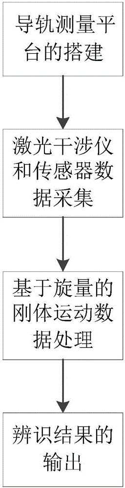
[0068] What is described below is a specific embodiment of the present invention, a laser measurement-based decoupling identification method for the straightness error of the guide rail base surface of a precision machine tool. The method specifically includes:

[0069] (1) Construction of the measurement platform

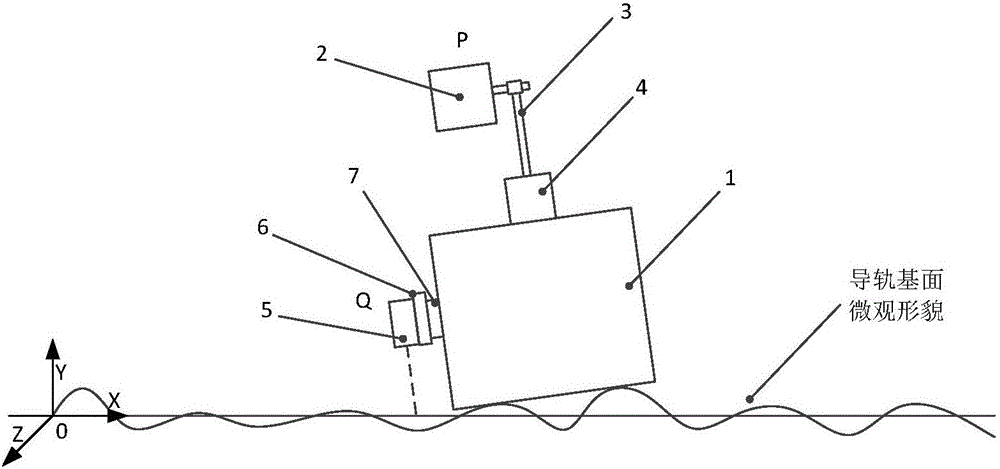
[0070] The measurement platform is mainly composed of two parts, basic components and measurement components, such as figure 2 As shown, the basic component includes a guide rail and a standard gauge block 1. The standard gauge block 1 is placed flat on the base surface of the guide rail to be measured, and the vertical straightness error of the base surface of the guide rail is reflected by the gauge block; the measurement component includes a laser interferometer And the laser displacement sensor 5 assembly, the mirror 2 of the laser interferometer is fixed on the gauge block through the magnetic base 4 and the connecting rod 3, and the straightness and angle er...


PUM


Abstract

The invention discloses a guide rail basal plane straightness error decoupling and identifying method. According to the method, a laser interferometer is utilized to measure straightness error and angle error of a standard gauge block in sliding and reading error measured by a laser displacement sensor, movement of all parts is expressed based on a spinor theory, and a guide rail basal plane straightness error value can be finally calculated out through an error decoupling data processing method; therefore, the purpose of measuring precise guide rail basal plane straightness error is achieved, and the guide rail basal plane straightness error decoupling and identifying method has an advantage of accuracy and certain practicability, and can be applied to researches of numerical control machine tool production quality detection analysis or machine tool precision analysis.

Description

technical field [0001] The invention belongs to the field of geometric error research of numerical control machine tools, and more specifically relates to a decoupling identification method for the straightness error of a base surface of a guide rail. Background technique [0002] At present, the instruments and tools for measuring the geometric error of machine tools mainly include laser interferometer, measuring ruler, level meter, collimator and dial gauge, etc. Laser interferometer is mainly used to measure the positioning error, straightness, angle error, Verticality, etc., but it is rarely used in the measurement of assembly rails, because its measurement is time-consuming and costly, and the use of traditional measurement tools can meet the requirements. The spirit level and dial indicator can be used to measure the straightness and angle in the guide rail assembly, and use the measurement results as a standard to adjust the assembly or scrape the base surface of the ...

Claims


Application Information

Patent Timeline
IPC IPC(8): G01B11/27
CPCG01B11/27
Inventor 刘红奇钟学敏李斌毛新勇常浩彭芳瑜蒋朝琨杨小龙
Owner HUAZHONG UNIV OF SCI & TECH
Why Eureka
Try Eureka