Measurement system, measurement method, evaluation method and compensation method for depth camera error

A technology of depth camera and error measurement, which is applied in the field of optical measurement, can solve the problems of depth camera error measurement and evaluation, and achieve the effect of accurate measurement and evaluation

Pending Publication Date: 2017-05-31
SHENZHEN ORBBEC CO LTD
View PDF8 Cites 27 Cited by
  • Summary
  • Abstract
  • Description
  • Claims
  • Application Information

AI Technical Summary

Problems solved by technology

[0003] The purpose of the present invention is to solve the problem of depth camera error measurement and evaluation, provide a system, measurement method and evaluation method for depth camera error measurement, and provide an error compensation scheme on this basis

Method used


Image

  • Measurement system, measurement method, evaluation method and compensation method for depth camera error
  • Measurement system, measurement method, evaluation method and compensation method for depth camera error
  • Measurement system, measurement method, evaluation method and compensation method for depth camera error

Examples


Embodiment 1

[0039] The depth measurement accuracy of the depth camera is mainly measured by two indicators: error and deviation. The error is used to measure the accuracy of the depth camera, and the standard deviation is used to measure the precision of the depth camera. Other precision representation methods may also be used in other embodiments.

[0040] (1) Error measurement method

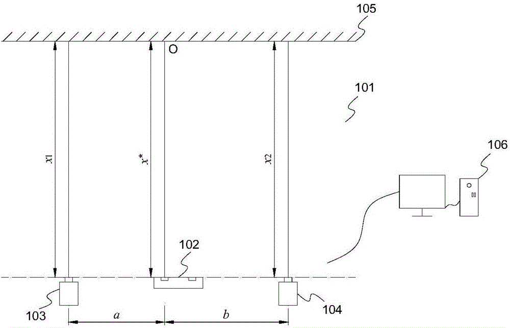
[0041] Error e(x * ) is represented by the difference between the measured value x* and the true value x, namely: e(x*)=x−x*. The acquisition of the true value is obtained by using a measuring device with higher precision, such as a laser range finder. When measuring, aim the depth camera at a plane, and place laser rangefinders on both sides of the depth camera, and the three are on the same baseline, such as figure 1 shown. In the actual measurement, the depth camera and the laser range finder are fixed on a movable base for synchronous movement.

[0042] The true value can also be obtained in othe...

Embodiment 2

[0050] Such as figure 1 Shown is a schematic diagram of a measurement system according to an embodiment of the present invention. The error measurement system 101 includes a depth camera 102 , laser range finders 103 and 104 , a measurement plane 105 and a computer 106 . The depth camera can be a depth camera based on structured light, TOF or binocular vision principles. Generally, the measurement accuracy (error) of the depth camera does not exceed 1% of its measurement distance, so the selected laser rangefinder is required to have a measurement accuracy higher than 1%, preferably at least an order of magnitude higher, that is, 0.1% , so that the data measured by the laser range finder is convincing when it is used as the real value.

[0051] Such as Figure 4As shown, when calculating the error in theory, it is necessary to measure the measured value and the real value of the same point or several points by the depth camera and the laser range finder. However, since the...

Embodiment 3

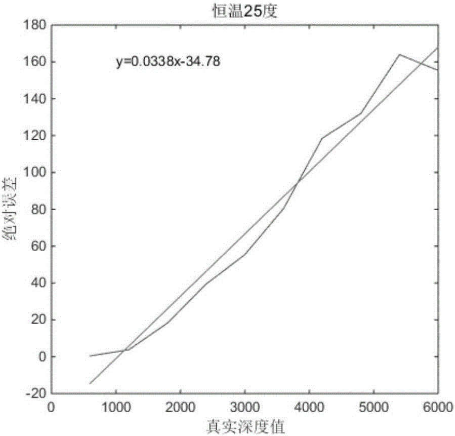
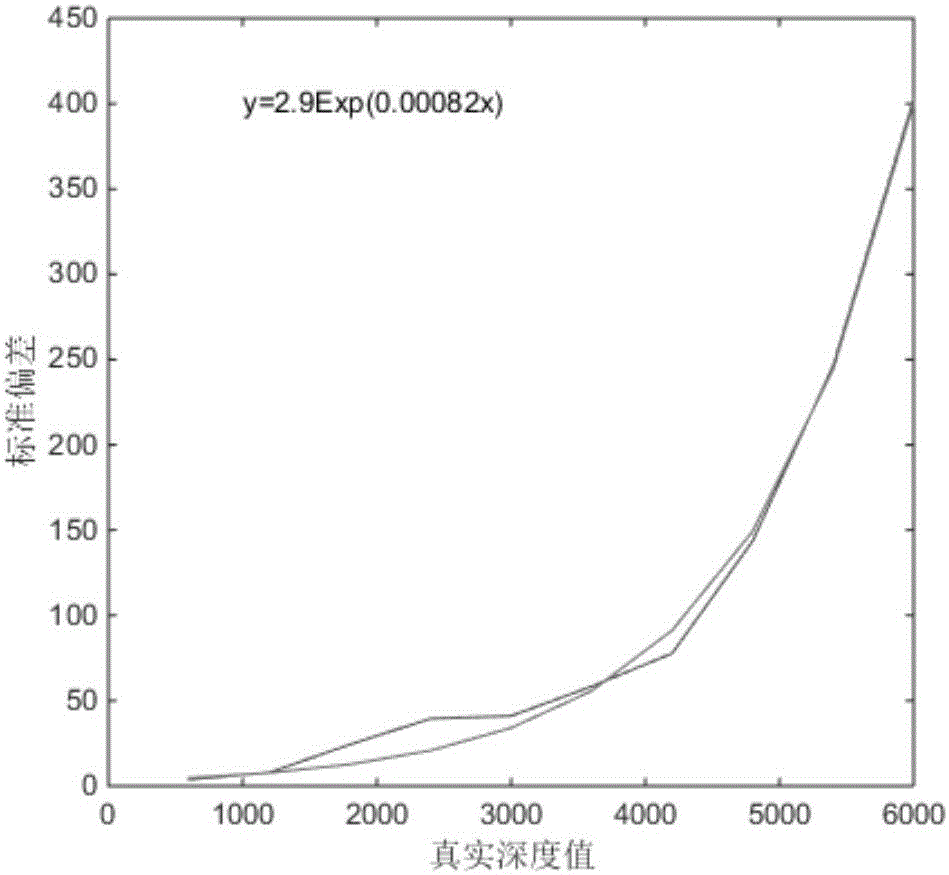
[0054] In this embodiment, the depth measurement error caused by the change of the measurement distance is mainly explained, and an evaluation method is given. Measurement distance variation is the biggest cause of error in depth cameras during normal use. Generally speaking, the measurement error increases with the increase of the measurement distance. In order to quantitatively evaluate the error change, in this embodiment, the measurement error of the depth camera at different measurement distances will be measured and quantitatively analyzed in combination with the above-mentioned error measurement system and measurement method.

[0055] In one embodiment, the measurement range of the depth camera 102 is 0.6-6m, and an error measurement is performed on the depth camera every 0.6m. In order to eliminate the influence of temperature, a temperature controller such as a semiconductor cooler (TEC) can be used to control the depth camera at a constant temperature.

[0056] The...


PUM


Abstract

The invention provides a measurement system, a measurement method, an evaluation method and a compensation method for a depth camera error. The measurement system for the depth camera error comprises a verifying device, a depth camera, a distance measurement device and a support, wherein the depth camera is used for measuring and obtaining a depth image of a measured plane; the measurement accuracy of the distance measurement device is higher than that of the depth camera; the support is used for fixing the depth camera and the distance measurement device and enabling measurement initial points/surfaces of the depth camera and the distance measurement device to be positioned in the same base line and directly face the measured plane. By adopting the measurement system provided by the invention, the measurement on the depth camera error can be realized, error and deviation can be calculated, and evaluation on the depth camera and compensation on the error can be carried out through the error and the deviation.

Description

technical field [0001] The invention relates to the technical field of optical measurement, in particular to a depth camera error measurement system and evaluation method. Background technique [0002] The depth camera can obtain the depth information of the target to realize 3D scanning, scene modeling, and gesture interaction. Compared with the currently widely used RGB camera, the depth camera is gradually being valued by all walks of life. When using the depth camera to measure the depth image of the target, clear and accurate depth information is an important indicator to measure the performance of the depth camera. However, due to the influence of temperature, light, and scene, the depth information obtained by the depth camera often has a large error. On the other hand, errors will inevitably occur during the manufacturing and assembly of depth camera components, which will also directly bring systematic errors to the measurement. Contents of the invention [0003...

Claims


Application Information

Patent Timeline
Patent Type & Authority Applications(China)
IPC IPC(8): G01C25/00
CPCG01C25/00
Inventor 刘龙黄源浩肖振中许星
Owner SHENZHEN ORBBEC CO LTD
Why Eureka
Try Eureka