Low-temperature superconductive reading circuit based on ERSFQ and reading system

A low-temperature superconducting and read-out circuit technology, applied in the direction of using electric/magnetic devices to transmit sensing components, can solve the problems of large heat load and weak anti-noise interference ability of circuit systems, achieve low power consumption, improve anti-noise Interference capability, the effect of reducing the number of transmission lines

Active Publication Date: 2017-05-31
SHANGHAI INST OF MICROSYSTEM & INFORMATION TECH CHINESE ACAD OF SCI
View PDF5 Cites 5 Cited by
  • Summary
  • Abstract
  • Description
  • Claims
  • Application Information

AI Technical Summary

Problems solved by technology

[0006] In view of the shortcomings of the prior art described above, the purpose of the present invention is to provide a low-temperature superconducting readout circuit and a readout system based on an ERSF...

Method used


Image

  • Low-temperature superconductive reading circuit based on ERSFQ and reading system
  • Low-temperature superconductive reading circuit based on ERSFQ and reading system
  • Low-temperature superconductive reading circuit based on ERSFQ and reading system

Examples


Embodiment 1

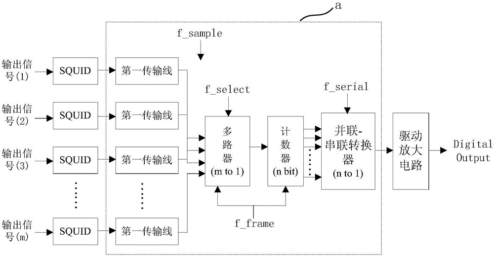
[0064] Such as figure 1 As shown, the present embodiment provides a low-temperature superconducting readout circuit based on an ERSFQ circuit, and the low-temperature superconducting readout circuit includes:

[0065] m superconducting quantum interference devices (SQUIDs), connected to the low-temperature superconducting sensor array, for converting the multiple output signals of the low-temperature superconducting sensor array into multiple SFQ pulse signals;

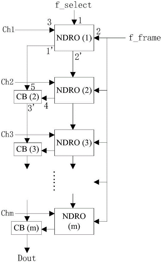
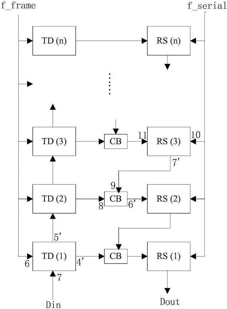
[0066] The ERSFQ circuit is connected to the m superconducting quantum interferometers, and is used to convert the multi-channel SFQ pulse signal into a binary single-channel pulse signal for output;

[0067] A driving amplifier circuit, connected to the ERSFQ circuit, for amplifying and outputting the binary single pulse signal;

[0068] Wherein, m is an integer greater than 1.

[0069] Preferably, in this embodiment, the low temperature superconducting sensor array includes a transition edge sensor (TES) array or ...

Embodiment 2

[0094] Such as Figure 7 As shown, the present embodiment also provides a readout system, which includes:

[0095] The low-temperature superconducting readout circuit based on the ERSFQ circuit described in Embodiment 1 is used to convert the output signal of the low-temperature superconducting sensor array into a binary single-channel pulse signal and amplify it;

[0096] The second transmission line is connected to the low-temperature superconducting readout circuit based on the ERSFQ circuit, and is used to transmit the output signal of the low-temperature superconducting readout circuit based on the ERSFQ circuit;

[0097] The room temperature readout circuit is connected with the second transmission line and is used to read out the output signal of the low temperature superconducting readout circuit based on the ERSFQ circuit.

[0098] Specifically, the second transmission line includes one or both of a superconducting transmission line or a Josephson junction transmissi...


PUM


Abstract

The present invention provides a low-temperature superconductive reading circuit based on the ERSFQ (Energy-efficient Rapid Single Flux Quantum) and a reading system. The circuit comprises: m superconduction quantum interference devices connected with a low-temperature superconductive sensor array and configured to convert the multi-output signals of the low-temperature superconductive sensor array to multiple SFQ pulse signals; an ERSFQ circuit connected with the m superconduction quantum interference devices and configured to convert the multiple SFQ pulse signals into the binary system one-way pulse signals for outputting; and a driving amplification circuit connected with the ERSFQ circuit and configured to perform amplification output of the binary system one-way pulse signals, wherein m is an integer of larger than 1. The low-temperature superconductive reading circuit based on ERSFQ and the reading system solve the problems that the reading amplification circuit is large in heat load and the circuit system anti-noise interference capability is bad in the prior art.

Description

technical field [0001] The invention belongs to the technical field of superconducting circuit design, in particular to a low-temperature superconducting readout circuit and a readout system based on an ERSFQ circuit. Background technique [0002] Low-temperature superconducting sensors have shown extremely high application value in the fields of quantum information, quantum optics, and astronomical detection due to their superior performance such as high detection efficiency and high energy resolution. With the development of low-temperature superconducting sensor research, the research and application of detectors are becoming more and more extensive. [0003] Since the output signal of the low-temperature superconducting sensor is relatively weak, it needs to be amplified in the low-temperature environment where it works before it can be read out by a traditional semiconductor readout circuit that works at room temperature. At present, the commonly used low-temperature r...

Claims


Application Information

Patent Timeline
IPC IPC(8): G01D5/14
CPCG01D5/14
Inventor 任洁应利良王镇
Owner SHANGHAI INST OF MICROSYSTEM & INFORMATION TECH CHINESE ACAD OF SCI
Why Eureka
Try Eureka