Device and method for detecting water level
A water level detection and water level technology, which is used in measuring devices, liquid/fluid solids measurement, liquid level indicators for physical variable measurement, etc., can solve the problems of high cost, complex circuit, poor measurement accuracy, etc. The effect of high precision and simple structure
- Summary
- Abstract
- Description
- Claims
- Application Information
AI Technical Summary
Problems solved by technology
Method used
Image
Examples
Embodiment 1
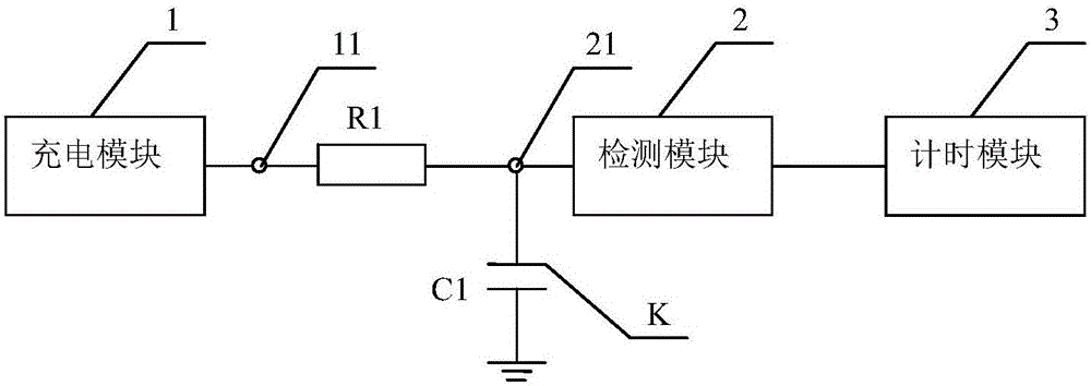
[0038] Embodiment 1: as figure 2 As shown, this embodiment provides a water level detection device, comprising:
[0039] The first resistor R1 is set between the charging terminal 11 and the detection terminal 21;
[0040] The capacitance probe K is arranged in the container 100 to be tested. In this embodiment, one end of the capacitance probe K is connected to the detection terminal 21, and the capacitance probe K and the ground respectively constitute two poles of a detection capacitance C1; The air and / or the liquid to be measured between the capacitance probe K and the ground are the medium of the detection capacitance C1 (when the container 100 is empty, the medium is air, and when the container 100 is full or the liquid to be measured in the container covers a part For capacitance probe K, the medium is air and the liquid to be measured).
[0041] A charging module 1, connected to the charging terminal 11, for charging the detection capacitor C1;
[0042] A detectio...
Embodiment 2
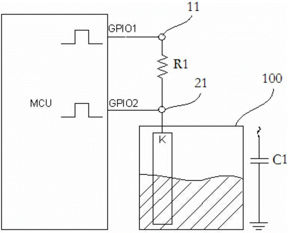
[0046] Embodiment 2: as image 3 As shown, in this embodiment, the charging module 1, the detection module 2, and the timing module 3 are all implemented by an MCU; for example, the above functions are simultaneously implemented by the same MCU, that is, at least one pin port of the MCU is configured as a charging output port ( image 3 GPIO1 port in ) and connected to the charging terminal 11, at least one pin port of the MCU is configured as a high-level interrupt trigger port ( image 3 GPIO2) and connected to the detection terminal 21, when the charging output port GPIO1 starts to output charging pulses (such as 5V step pulses), the timing module 3 in the MCU starts timing until the detection terminal 21 detects After a high level (such as any value in 3.5V~5V), an interrupt is triggered, and the timing module 3 stops timing, and records the time in the memory, and then obtains the water level height data according to the pre-calibrated time-water level comparison table. ...
Embodiment 3
[0048] Embodiment 3: as Figure 5 As shown, this embodiment provides the method flow for detecting the water level using the water level detection device provided in Embodiment 2, including the following steps,
[0049] Calibration stage: After the length of the capacitance probe is determined, the time-dielectric constant (capacitance) correspondence relationship is tabulated and stored in advance; after the capacitance probe is installed in the container to be tested, according to the actual placement position of the capacitance probe in the container to be tested , calibrate the corresponding relationship between the charging time and the water level, formulate a time-water level comparison table (in some embodiments, it can also be a time-capacitance-water level comparison table), and store the table in the storage module.
[0050] When calibrating, at least zero water level and full water level should be calibrated; it should be noted that the zero water level here does n...
PUM
 Abstract
Description
Claims
Application Information
 - R&D
- Intellectual Property
- Life Sciences
- Materials
- Tech Scout
- Unparalleled Data Quality
- Higher Quality Content
- 60% Fewer Hallucinations
Browse by: Latest US Patents, China's latest patents, Technical Efficacy Thesaurus, Application Domain, Technology Topic, Popular Technical Reports.
© 2025 PatSnap. All rights reserved.Legal|Privacy policy|Modern Slavery Act Transparency Statement|Sitemap|About US| Contact US: help@patsnap.com


