
Thermo-optic non-localized angle double-slit interference method and system

A technique of double-slit interference and localization, applied in the field of optics

Active Publication Date: 2018-05-25
CHINA UNIV OF GEOSCIENCES (BEIJING)
View PDF10 Cites 0 Cited by
  • Summary
  • Abstract
  • Description
  • Claims
  • Application Information

AI Technical Summary

Problems solved by technology

[0006] At present, the field of application technology using photon orbital angular momentum as an information carrier is still in a blank stage, and many application technologies are only in the stage of theoretical discussion, waiting for in-depth development and research by researchers in this field

Method used


Image

  • Thermo-optic non-localized angle double-slit interference method and system
  • Thermo-optic non-localized angle double-slit interference method and system
  • Thermo-optic non-localized angle double-slit interference method and system

Examples


Embodiment 1

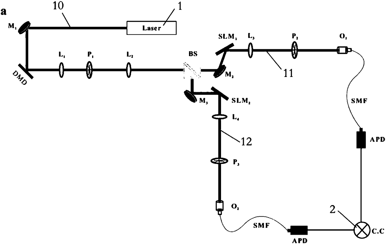
[0065] like Figure 1-2 As shown in the figure, the present embodiment provides a thermal-optical non-localized angle double-slit interference system, which includes a thermal light source, a non-polarizing beam splitter BS, a spatial light modulator, a single-photon detector, and a computer 2 arranged in sequence on the optical path. ;

[0066] a thermal light source for emitting an incoherent thermal beam 10;

[0067] The incoherent thermal light beam 10 is evenly divided into a first light beam 11 and a second light beam 12 according to the light intensity by the non-polarizing beam splitter BS;

[0068] The optical path of the first light beam 11 is the first optical path,

[0069] The optical path of the second light beam 12 is the second optical path;

[0070] The components on the first optical path and the second optical path are symmetrically arranged;

[0071] Spatial light modulators are used to change the orbital angular momentum of photons; single-photon detec...

Embodiment 2

[0094] This embodiment provides a thermal-optical non-localized angle double-slit interference method using the above system, and the thermal-optical non-localized angle double-slit interference method includes the following steps:

[0095] S1. The incoherent thermal beam 10 is equally divided into a first beam 11 and a second beam 12;

[0096] S2. The first light beam 11 and the second light beam 12 respectively pass through the first light path and the second light path, wherein the first light path and the second light path are symmetrically arranged;

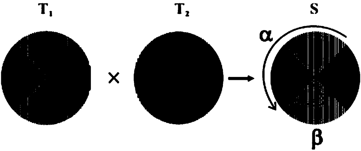
[0097] S3. Load different orbital angular momentum values ​​to the first optical path and the second optical path by loading different fork patterns on the spatial light modulator SLM in the two optical paths;


PUM


Abstract

The invention provides a calorescence nonlocalized angle double-slit interference method and system. The system comprises a thermal light source, an unpolarized beam splitter, a spatial light modulator, a single photon detector and a computer which are arranged in sequence on light paths; components on a first light path and a second light path are arranged symmetrically. According to the calorescence nonlocalized angle double-slit interference method and system, by utilizing the incoherent thermal light source, angle double-slit interference utilizing correlated characteristics of incoherent thermal light source orbital angular momentum domain is achieved for the first time; the requirement for light source coherence is reduced, accordingly the application range is widened, and the nonlocalized detection for an object to be detected can be achieved. As for the two light paths in the system, one light path can be called as an object light path, and the other light path can be called as a reference light path.

Description

technical field [0001] The invention relates to the field of optical technology, in particular to a thermo-optical non-localized angle double-slit interference method and system. Background technique [0002] In 1909, Poynting discovered that light waves have spin angular momentum. In 1992, Allen et al. from Leidon University discovered that photons carry orbital angular momentum (OAM) in addition to spin angular momentum. [0003] In 2002, the Padgett group of the University of Glasgow realized the photon orbital angular momentum separation technology experimentally, and pointed out that the orbital angular momentum as the information carrier can greatly improve the communication capacity of a single photon, mainly because the photon orbital angular momentum is an infinite dimension. of. [0004] In 2001, Zeilinger's group demonstrated for the first time experimentally that two-photons produced by spontaneous parametric downconversion exhibit orbital angular momentum enta...

Claims


Application Information

Patent Timeline
Patent Type & Authority Patents(China)
IPC IPC(8): G01J3/45G01J1/44
CPCG01J1/44G01J3/45G01J2001/442
Inventor 高禄
Owner CHINA UNIV OF GEOSCIENCES (BEIJING)
Learn More