Dynamic torque detection system

A detection system and dynamic torque technology, applied in force/torque/power measuring instrument calibration/testing, measuring devices, instruments, etc., can solve the problems of low measurement accuracy, improve measurement accuracy, facilitate replacement, and strong impact resistance effect of ability

Pending Publication Date: 2017-05-31
SICHUAN DONG TAI MACHINERY MFG CO LTD
View PDF8 Cites 15 Cited by
  • Summary
  • Abstract
  • Description
  • Claims
  • Application Information

AI Technical Summary

Problems solved by technology

[0005] The object of the present invention is to provide a dynamic torque detection system using continuous braking to solve the problem of low measurement accuracy of the existing torque wrench tester due to instantaneous braking

Method used


Image

  • Dynamic torque detection system
  • Dynamic torque detection system

Examples


Embodiment 1

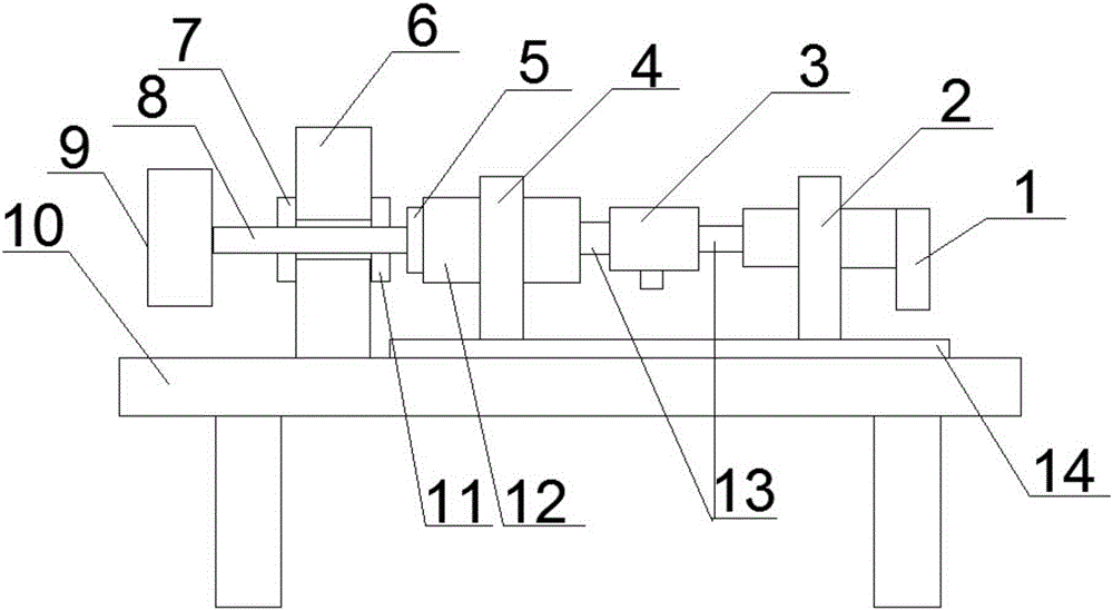
[0023] Such as figure 1 As shown, the dynamic torque detection system includes a machine base 10 and a torque sensor 3, an electric and pneumatic torque wrench 1 is fixedly installed on the said machine base 10, and one end of the torque sensor 3 is connected with the electric and pneumatic torque wrench through a shaft coupling 13. The output shaft of the wrench 1 is connected, and the other end of the torque sensor 3 is connected with a sleeve 12 through a coupling 13, and the sleeve 12 is rotatably fixed on the machine table 10; Torque braking device for continuous braking.

[0024] The working process of the present invention: start the switch of the electric and pneumatic torque wrench 1, the electric and pneumatic torque wrench 1 rotates at high speed, drives the torque sensor 3 to rotate through the shaft coupling 13, and the torque sensor 3 drives the sleeve 12 to rotate through the shaft coupling 13, Thus, the torque braking device connected to the sleeve 12 is drive...

Embodiment 2

[0028] Based on Embodiment 1, the torque braking device includes bolts 8 and bolts 8 for tightening workpieces 9; the machine table 10 is provided with a sliding guide rail 14, and the electric and pneumatic torque wrench 1 is fixed on the sliding guide rail 14 by the clamping mechanism 2 Above, the sleeve 12 is fixed on the sliding guide rail 14 through the bearing 4 . Continuous braking can be realized by tightening the bolt 8, and when the sleeve 12 drives the bolt 8 to gradually tighten the workpiece 9, the sleeve 12 will follow the bolt 8 to move, therefore, by setting the sliding guide rail 14 to ensure that the electric and pneumatic torque wrench 1 and the torque sensor 3 move together with the bolt. In addition, the slide rail 14 facilitates replacement of the bolt 8 , the sleeve 12 and the torque sensor 3 .

Embodiment 3

[0030] Based on the above-mentioned embodiment, the machine table 10 is provided with a fixed plate 6, and a through hole is opened on the fixed plate 6. One end of the bolt 8 is connected to the sleeve 12 through the connector 5, and the other end is connected to the workpiece 9 through the through hole. . By setting the fixing plate 6, it can be ensured that the bolts 8 passing through the fixing plate 6 will not deviate during the tightening process.


PUM


Abstract

The invention discloses a dynamic torque detection system, comprising a bench and a torque sensor; an electrical-pneumatic torque wrench is fixedly mounted on the bench; one end of the torque sensor is connected with an output shaft of the electrical-pneumatic torque wrench; the other end of the torque sensor is connected with a sleeve through a coupling; the sleeve is rotationally fixed on the bench and is connected with a torque brake device that may provide continuous braking for torque. By providing the torque brake device that may provide continuous braking for torque to detect a torque peak, measurement precision is improved; the torque brake device is arranged as a bolt, continuous braking is achieved by tightening the bolt; compared with simulated bolts, the dynamic torque detection system as a calibrator allows an actually used bolt to be sued in the detection process, and the actual condition can be simulated to maximum extent.

Description

technical field [0001] The invention belongs to the technical field of torque verification, and in particular relates to a dynamic torque detection system. Background technique [0002] Torque detector is an instrument used for verification (calibration) of various manual, electric and pneumatic torque wrenches, and is an important measuring instrument for controlling product quality. The traditional verification method adopts a static method, that is, the torque wrench is connected with a static torque sensor through simulated bolts. The simulated bolt is one or several pairs of impact buffer devices with butterfly spring coils. The friction force and the reaction force of the spring coils along the axial direction are all dynamic changes, which seriously affect the measurement accuracy. When the method verifies or calibrates the torque wrench, the torque sensor is not only subjected to the torque from the torque wrench, but also is subjected to additional torque caused by...

Claims


Application Information

Patent Timeline
Patent Type & Authority Applications(China)
IPC IPC(8): G01L25/00
CPCG01L25/003
Inventor 冯文泰
Owner SICHUAN DONG TAI MACHINERY MFG CO LTD
Why Eureka
Try Eureka