

Glass coating wire detector
A technology of glass coating and testing instruments, applied in the direction of material magnetic variables, etc., can solve the problems of high production costs, achieve the effects of simplifying analog circuits, reducing signal-to-noise ratio, and ensuring robustness
- Summary
- Abstract
- Description
- Claims
- Application Information
AI Technical Summary
Problems solved by technology
Method used
Image

Examples
Embodiment Construction
[0016] The present invention will be further described below in conjunction with drawings and embodiments.
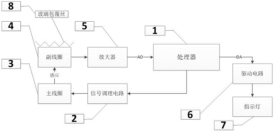
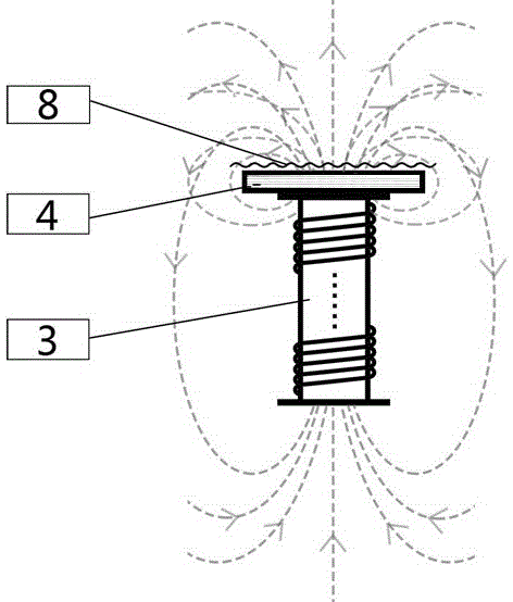
[0017] Such as figure 1 As shown, the glass-coated wire detection instrument of the present invention includes: a processor system 1 , a signal integration circuit 2 , a main coil 3 , a secondary coil 4 , an amplifier 5 , a drive circuit 6 , and an indicator light 7 . There is only one primary and secondary coil respectively.
[0018] In this embodiment, the processor MCU (1) adopts a 32-bit Cortex-M3 processor with an instruction execution capability of 150DMIPS and an AD converter with a rate of 6Msps. Processor MCU (1) generates a sinusoidal signal with fixed frequency (200HZ) and fixed amplitude (2.5V). The function of this signal is to allow the disturbance effect of the glass-coated wire on the magnetic field to be intuitively reflected through this sinusoidal carrier.
[0019] The sinusoidal signal is transformed into a ladder-type analog signal through DA con...
PUM
 Abstract
Description
Claims
Application Information