
Dynamic testing device for isolation ability of cementing sheath and experimental method

A technology for dynamic testing and cementing cement, applied in the field of cementing in petroleum engineering, can solve problems such as single testing method, and achieve the effect of improving experimental accuracy and enriching monitoring methods.

Active Publication Date: 2017-05-31
SOUTHWEST PETROLEUM UNIV
View PDF13 Cites 30 Cited by
  • Summary
  • Abstract
  • Description
  • Claims
  • Application Information

AI Technical Summary

Problems solved by technology

[0008] Secondly, for the simulation of downhole complex situations, the previous devices only simulated the situation where the casing is centered, but there are few examples for eccentricity, mud mixing, pot-bellied holes, uneven filling, horizontal wells, double-layer casings, and packer setting positions. The simulation of cement sheath and corrosion, compared with the regular wellbore, the sealing performance of the cement sheath in the complete filling and the actual downhole situation will not be the same
[0009] Finally, the test method is single, and whether "gas channeling" occurs is used as the basis for observing whether the sealing capacity of the cement sheath is damaged or not.

Method used


Image

  • Dynamic testing device for isolation ability of cementing sheath and experimental method
  • Dynamic testing device for isolation ability of cementing sheath and experimental method
  • Dynamic testing device for isolation ability of cementing sheath and experimental method

Examples


Embodiment Construction

[0048] The present invention will be further described below in conjunction with drawings and embodiments.

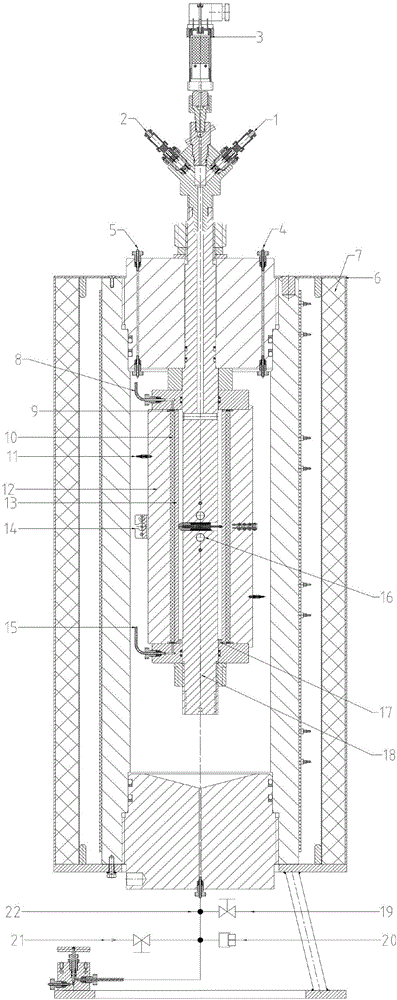
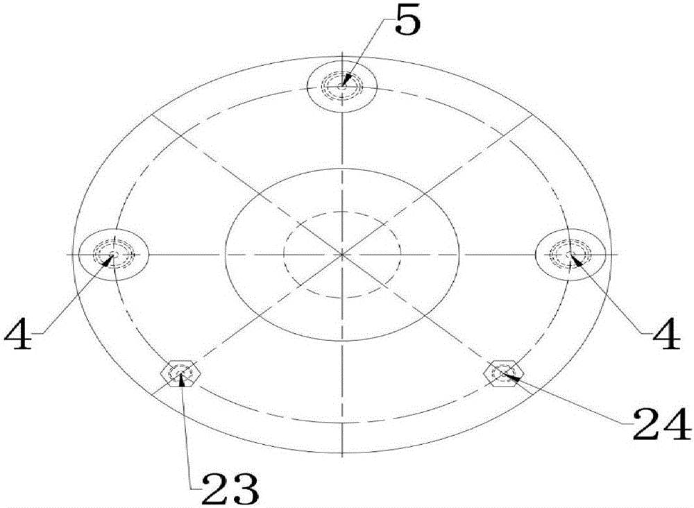
[0049] see figure 1 , figure 2 .

[0050] The utility model relates to a dynamic test device for sealing capacity of a cement sheath, which includes a working platform and a test main body.

[0051] The working platform has a computer, and the computer is provided with a pressure and temperature control terminal.

[0052] The test body is located on the bracket. The outside of the test body is the metal cover 6 and the insulation layer 7. The upper and lower parts are the kettle cover, and the middle part is the kettle body. The inside of the kettle body is the simulated formation 12-cement sheath 10-casing 13 from the outside to the inside. The simulated formation 12 is equipped with a circumferential displacement meter 14 and an acoustic wave receiving probe 11, and the annular space between the simulated formation and the casing is an annular space for cement she...


PUM


Abstract

The invention discloses a dynamic testing device for the isolation ability of a cementing sheath and an experimental method. The device comprises a working platform and a testing main body, wherein the working platform comprises a computer; the testing main body comprises kettle covers on the top and at the bottom; the middle part of the testing main body is taken as a kettle body; the kettle body comprises an analog stratum, a cement sheath and a casing from outside to inside in sequence; a solid column body is inserted into the casing; filter screens and eccentric bases are arranged on contact parts between the kettle covers and a stratum-cement sheath-casing end face. The method comprises the following steps: preparing cement slurry, and filling the cement slurry into an annular space; waiting on cement setting, curing and hardening into a sheath; changing the temperature and pressure in the casing, testing radial displacement of the casing and peripheral displacement of the analog stratum, and monitoring the airtightness failure condition of the cement sheath through an acoustic wave testing curve; detecting micro-cracks generated in the cement sheath and micro-annuluses on interfaces I and II, and analyzing the airtightness failure form of the cement sheath. The dynamic testing device is reliable in principle, and is easy and convenient to operate; integrated curing is performed in an experimental process, and more data support and a theoretical basis are provided for researches for testing the isolation ability of the cementing sheath.

Description

technical field [0001] The invention relates to a dynamic testing device and an experimental method for dynamically monitoring the sealing ability of a cement sheath under different working conditions in the field of petroleum engineering well cementing. [0002] technical background [0003] Oil and gas well cementing operation refers to the process of injecting oil well cement into the annular space between the downhole casing and the formation to make the cement slurry condense and solidify within the design time to form a cement sheath with interlayer isolation ability. The role of the cement sheath in the downhole is not only to seal the formation, but also to suspend and protect the casing and to prolong the production cycle of the whole well. [0004] However, the service environment of the cement sheath in the underground is very harsh. During the actual construction on site, working conditions such as casing eccentricity, pot-bellied wellbore, mud mixing, and uneven...

Claims


Application Information

Patent Timeline
IPC IPC(8): G01N33/38
CPCG01N33/383
Inventor 张兴国苏东华李早元刘健郭小阳陈一健杜建波唐毅肖夏
Owner SOUTHWEST PETROLEUM UNIV
Learn More