Method for generating extreme waves at specified positions in experimental water tank

A technology for specifying position and wave, applied in the field of marine engineering and hydrodynamic experiment research, can solve the problems of inability to judge the wave surface condition of the focal point, the deviation of the position and preset position of extreme wave generation, and waste of cost.

Active Publication Date: 2017-10-20
DALIAN UNIV OF TECH
View PDF7 Cites 11 Cited by
  • Summary
  • Abstract
  • Description
  • Claims
  • Application Information

AI Technical Summary

Problems solved by technology

In addition, in the existing methods of generating extreme waves, it is impossible to judge the wave surface conditions upstream and downstream of the focus point, and there may be early and secondary breakage du

Method used


Image

  • Method for generating extreme waves at specified positions in experimental water tank
  • Method for generating extreme waves at specified positions in experimental water tank
  • Method for generating extreme waves at specified positions in experimental water tank

Examples


Embodiment 1

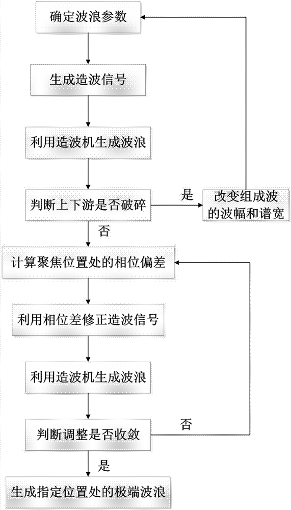
[0068] A method of generating extreme waves at a designated location in an experimental tank comprising the steps of:

[0069] A. Generate initial wave-making signal and initial wave-making

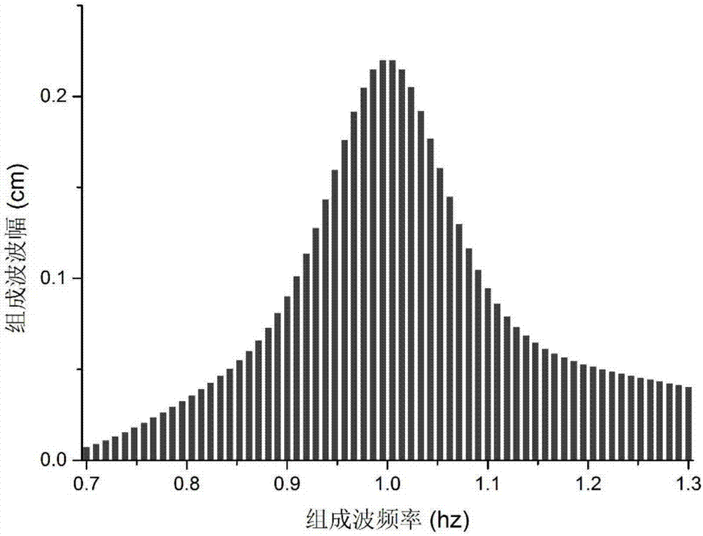
[0070] The wave parameters are determined according to the tank parameters in the laboratory, and the phase-focused waves are used to use the linear dispersion relationship to reversely calculate the motion process of the wave maker, so that the component waves reach the same phase at the specified position, and the superposition produces extremely large waves. On the free water surface, the wave surface Eta(x,t) of the wave at any point is expressed as the result of the superposition of regular waves of different frequencies:

[0071]

[0072] In the formula, A j Represents the amplitude of the jth component wave, k j Represents the wavenumber of the jth component wave, ω j represents the frequency of the jth component wave, represents the initial phase of the jth component wave....

Embodiment 2

[0112] In order to make the object, technical solution and advantages of the present invention clearer, the present invention will be further described in detail below in conjunction with the accompanying drawings and examples of implementation. It should be understood that the specific implementation examples described here are only used to explain the present invention, and are not intended to limit the present invention.

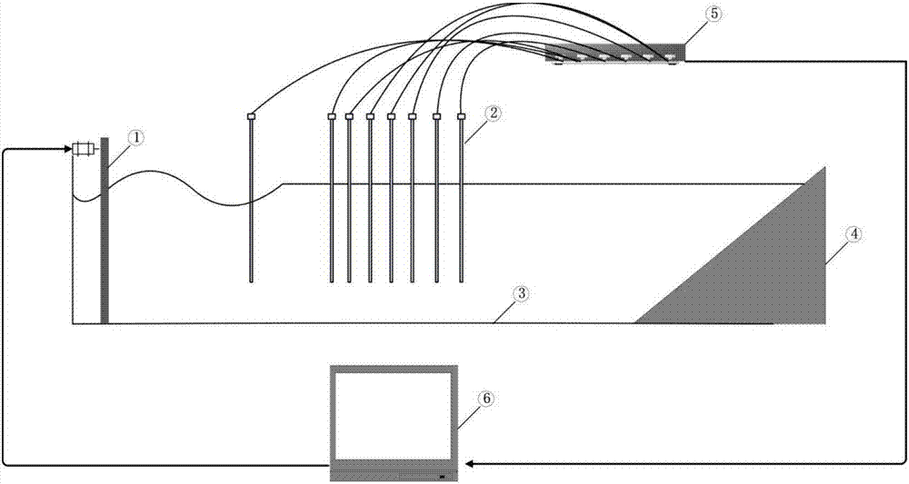
[0113] established as figure 2 The shown wave-making control system includes: an experimental water tank, a pusher-type wave-making machine, a wave-dissipating device, a wave height meter, a wave-height meter signal collector, and a computer equipped with a wave-making system and an acquisition system. Wherein, the wave height meter is connected with the wave height meter collector; the wave height meter signal collector is connected with the computer; and the wave maker is connected with the computer.

[0114] The sample experiment is carried out in th...


PUM


Abstract

The invention relates to a method for generating extreme waves at specified positions in an experimental water tank and belongs to the technical field of ocean engineering and hydrodynamic experimental research. The method comprises steps of: determining a wave parameter according to a water tank parameter in a laboratory, generating a wave-generating signal, inputting the wave-generating signal into a wave-generating system for initial wave making, determining whether the waves are broken, and changing the wave amplitude and the spectrum width constituting the waves if so in order to re-determine the wave parameter; if not, calculating the phase deviation at a focus position by using all-phase Fourier transform, correcting the wave-generating signal by using a phase difference, generating waves by a wave generator, determining whether the phase adjustment at the focus position converges, and recalculating the phase deviation at the focus position if not; if so, generating the extreme waves at the specified positions. The method flexibly controls the effect position of the extreme waves and a structure model in the water tank and precisely generates extreme waves in different forms at designated positions of the water tank, thereby improving experimental efficiency and precision.

Description

technical field [0001] The invention belongs to the technical field of marine engineering and hydrodynamic experiment research, and relates to a method for generating extreme waves at a designated position in an experimental water tank Background technique [0002] Extreme waves are single abnormally large waves that suddenly appear on the sea surface, which have brought serious harm to human life and production activities. In order to avoid the damage of extreme waves to offshore structures, we can simulate extreme waves in the experimental tank to provide a basis for the design of marine engineering structures. When simulating the effect of extreme waves on structures in a tank, the structural model is often bulky, expensive, and inconvenient to move. Therefore, there is now a need for a method that can precisely control the focus position of the wave, and generate extreme waves of different shapes at the specified position, so as to accurately simulate the impact of extr...

Claims


Application Information

Patent Timeline
IPC IPC(8): G01M10/00
CPCG01M10/00
Inventor 马玉祥牛旭阳董国海马小舟
Owner DALIAN UNIV OF TECH
Why Eureka
Try Eureka