
A Timing Design Method for Modulation Domain Measurement in Short Time Interval

A design method and modulation domain technology, applied in the field of short-time interval modulation domain measurement sequence design, can solve the problems of increasing measurement time, constraints, time errors, etc., and achieve the effects of improving efficiency, low cost, and simplifying timing

Active Publication Date: 2019-11-12
THE 41ST INST OF CHINA ELECTRONICS TECH GRP
View PDF12 Cites 0 Cited by
  • Summary
  • Abstract
  • Description
  • Claims
  • Application Information

AI Technical Summary

Problems solved by technology

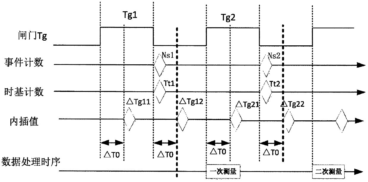
However, since the determination of the delay time is still based on the low gate as the time reference, the size of the gate must be greater than ΔT0 to meet the processing of the delay time of ΔT0, that is to say, ΔT0 limits the gate design and cannot be less than ΔT0
Moreover, there is a certain time error in the actual circuit. In the actual test, the value of ΔT0 will fluctuate in a small range according to the time of retriggering. Therefore, the delay time setting should be larger than ΔT0, and the measurement time will be further increased.
[0010] Therefore, according to the method of processing high gate channel data during low gate period and processing low gate channel data during high gate period, the time interval of modern technical solutions for modulation domain analysis is limited to more than 100 ns, or even higher, which also restricts the short time of modulation domain analysis. Interval requirements for frequency-agile and linear-frequency measurements

Method used


Image

  • A Timing Design Method for Modulation Domain Measurement in Short Time Interval
  • A Timing Design Method for Modulation Domain Measurement in Short Time Interval
  • A Timing Design Method for Modulation Domain Measurement in Short Time Interval

Examples


Embodiment Construction

[0032] The following will clearly and completely describe the technical solutions in the embodiments of the present invention with reference to the accompanying drawings in the embodiments of the present invention. Obviously, the described embodiments are only some, not all, embodiments of the present invention. Based on the embodiments of the present invention, all other embodiments obtained by persons of ordinary skill in the art without making creative efforts belong to the protection scope of the present invention.

[0033] The time sequence processing of short time interval measurement in the prior art is limited by the size of the gate, and the time for one measurement is long and the efficiency is low.

[0034] The present invention proposes an effective measurement data output feedback mechanism, abandons the traditional method of processing data during the high and low periods of the time gate, gets rid of the time limit of the gate, and further shortens the time inter...


PUM


Abstract

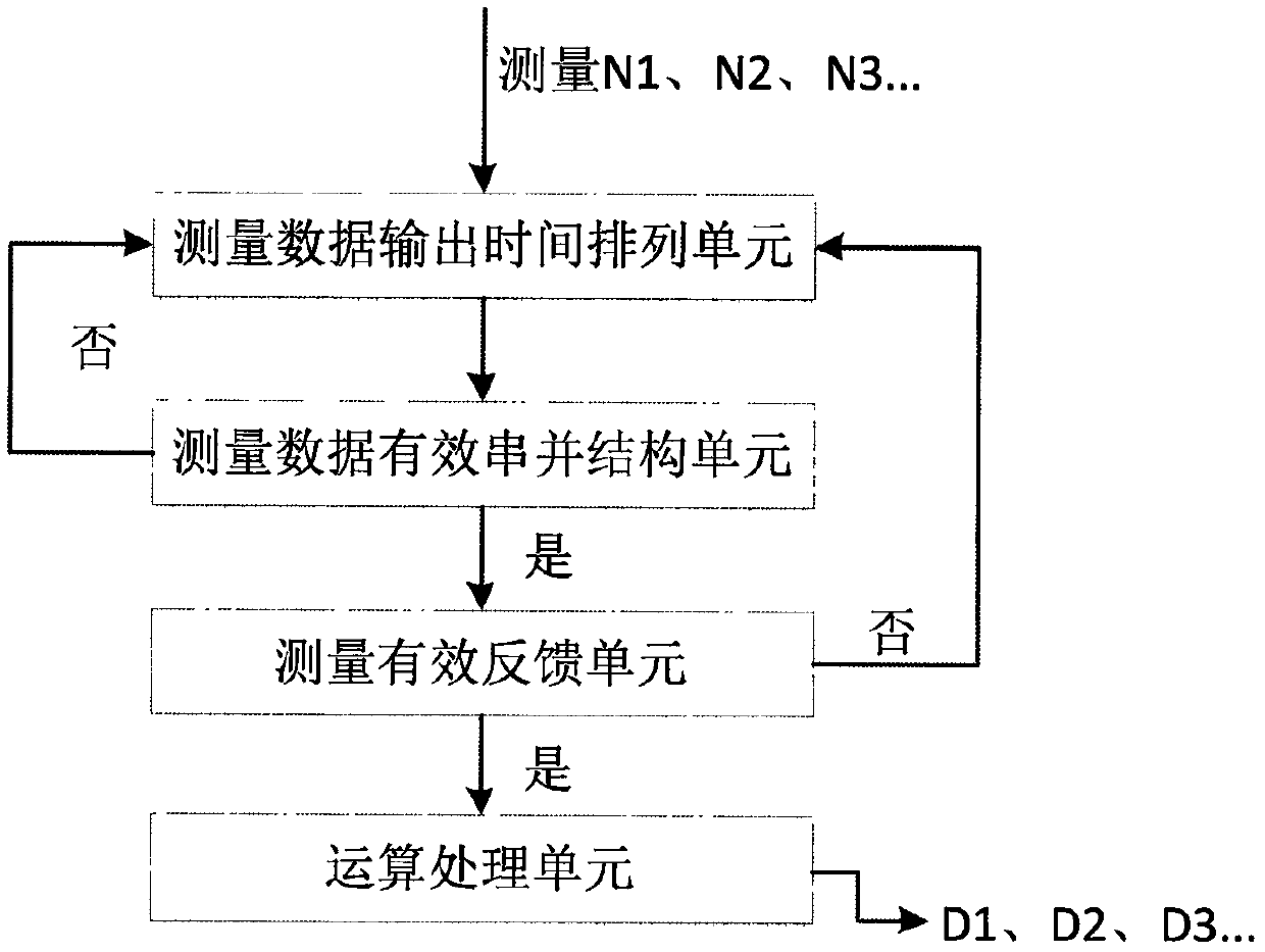
The present invention proposes a short time interval modulation domain measurement sequence design method, including: measurement data output time arrangement unit, each data effective serial parallel structure unit, measurement effective feedback signal generation unit, operation processing unit; the measurement data output time The arrangement unit arranges the data of various parameters in one measurement of each measurement unit in chronological order, and designs each data effective serial-parallel structural unit according to this order; the effective serial-parallel structural unit of each data is the output of each measurement parameter Construct a series-parallel process based on the contextual relationship, select the moment when the last measurement data is output as the end of an effective measurement process; the measurement effective feedback signal generation unit uses the feedback signal to start the measurement unit; the operation processing unit is responsible for the realization of the algorithm The data measured by the two channels of the high and low gates are seamlessly integrated, and the measured data is read through the high-speed interface, and is responsible for the final calculation, processing and display of the data.

Description

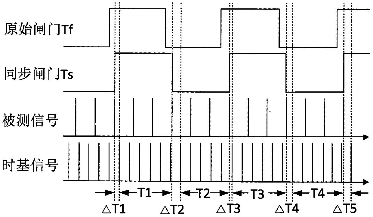
technical field [0001] The invention relates to the technical field of testing, in particular to a timing sequence design method for short time interval modulation domain measurement. Background technique [0002] In the field of electronic measurement, with the development and application of pulse modulation, digital modulation, linear modulation, and frequency-agile modulation technologies, higher requirements are placed on modern modulation domain analyzers. In order to meet new requirements, modern modulation domain analysis needs to have measurement requirements such as shorter sampling interval, larger analysis bandwidth, and higher resolution. Modulation domain analysis accurately characterizes the transient characteristics of the signal under test through high-speed continuous measurement without dead zone. The typical measurement sequence diagram is as follows: figure 1 shown. [0003] figure 1 Among them, the synchronous gate Ts is generated after synchronizing ...

Claims


Application Information

Patent Timeline
Patent Type & Authority Patents(China)
IPC IPC(8): G01R29/00G01R29/06
CPCG01R29/00G01R29/06
Inventor 刘强毛黎明丁建岽任水生杨帆
Owner THE 41ST INST OF CHINA ELECTRONICS TECH GRP
Learn More