Multi-beam scanning device and multi-bean scanning method

A scanning device and multi-beam technology, applied in the field of radar, can solve problems such as not being able to be applied in large quantities, lack of matching components, and needs to be improved, and achieve the effects of fast scanning speed, improved reliability, and wide scanning angle

Pending Publication Date: 2017-05-31
武汉灵途传感科技有限公司
View PDF6 Cites 33 Cited by
  • Summary
  • Abstract
  • Description
  • Claims
  • Application Information

AI Technical Summary

Problems solved by technology

[0003] 2D and 3D laser radars can provide information in three-dimensional space. At present, the main technical solutions are realized by scanning the optical path of a single-point laser rangefinder or a multi-point laser rangefinder. How to realize it quickly and reliably Scanning has become a technical bottleneck
[0012] iv. Waveguide phased array scanning (withou...

Method used


Image

  • Multi-beam scanning device and multi-bean scanning method
  • Multi-beam scanning device and multi-bean scanning method
  • Multi-beam scanning device and multi-bean scanning method

Examples


Embodiment Construction

[0047] In order to make the object, technical solution and advantages of the present invention clearer, the present invention will be further described in detail below in conjunction with the accompanying drawings and specific embodiments. It should be understood that the specific embodiments described here are only used to explain the present invention, not to limit the present invention.

[0048] In the following text, many aspects of the invention will be better understood with reference to the accompanying drawings. Components in the figures are not necessarily drawn to scale. Instead, emphasis is placed on clearly illustrating the components of the invention. Furthermore, like reference numerals indicate corresponding parts throughout the several views of the drawings.

[0049] As used herein, the word "exemplary" or "illustrative" means serving as an example, instance, or illustration. Any implementation described herein as "exemplary" or "illustrative" is not necessa...


PUM


Abstract

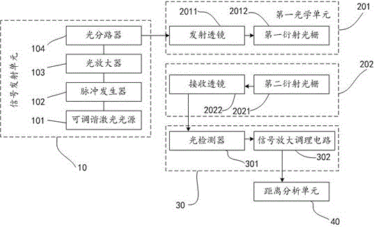
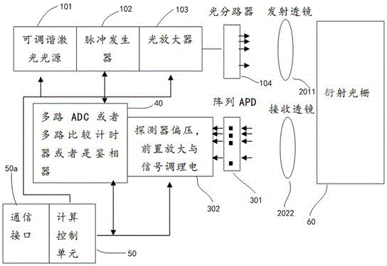
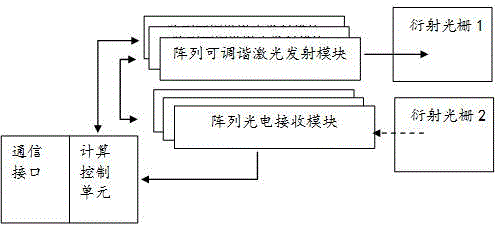
The invention relates to the technical field of radars, in particular to a multi-beam scanning device and a multi-bean scanning method. The device comprises a signal transmitting unit 10, a fist optical unit 201, a second optical unit 202, a signal receiving unit 30 and a distance analysis unit 40. The multi-beam scanning device and the multi-bean scanning method provided by the invention are in a diffraction-based laser radar scanning mode; a fixed diffraction grating is used; the scanning of a laser radar is realized by changing a diffraction angle by changing laser wavelength; a mechanical movement part can be avoided in the mode; the scanning angle is wide, for example, the scanning angle can reach +/-4 degrees; the scanning speed is high, for example, the scanning speed can exceed 10 kHz, and meanwhile, the reliability is greatly improved.

Description

technical field [0001] The invention relates to the field of radar technology, in particular to a multi-beam scanning device and a multi-beam scanning method. Background technique [0002] LiDAR uses emitted laser light to irradiate the target, and analyzes distance and velocity information through the delay, phase or displacement of the target's return laser. This is a technology with a long history. In recent years, with the development of industries such as 3D printing measurement, map mapping, assisted and automatic driving, and drones, it has also driven the rapid development of lidar technology and applications. [0003] 2D and 3D laser radars can provide information in three-dimensional space. At present, the main technical solutions are realized by scanning the optical path of a single-point laser rangefinder or a multi-point laser rangefinder. How to realize it quickly and reliably Scanning has become a technical bottleneck. [0004] Existing scanning techniques i...

Claims


Application Information

Patent Timeline
IPC IPC(8): G01S7/481
CPCG01S7/4817
Inventor 李传文
Owner 武汉灵途传感科技有限公司
Why Eureka
Try Eureka