Laser radar system based on MEMS micro mirror scanning

A laser radar and micromirror technology, applied in the field of radar, can solve the problems of difficult control, inconvenience, difficult control of timing algorithms, etc., and achieve the effect of low cost and high measurement frequency

Pending Publication Date: 2017-05-31
LEISHEN INTELLIGENT SYST CO LTD
View PDF10 Cites 33 Cited by
  • Summary
  • Abstract
  • Description
  • Claims
  • Application Information

AI Technical Summary

Problems solved by technology

[0002] The current multi-line laser radar realizes multi-line scanning by multiple transmitting lasers and multiple receiving detectors, such as the laser radar VLP-16 of Verlodyne Company of the United States, which requires 16 lasers to transmit and receive, 16 transmitting circuits and receiving circuits. It is difficult to deal with, the timing algori

Method used


Image

  • Laser radar system based on MEMS micro mirror scanning
  • Laser radar system based on MEMS micro mirror scanning
  • Laser radar system based on MEMS micro mirror scanning

Examples


Embodiment Construction

[0032] In order to make the object, technical solution and advantages of the present invention clearer, the present invention will be further described in detail below in conjunction with the accompanying drawings and embodiments. It should be understood that the specific embodiments described here are only used to explain the present invention, not to limit the present invention.

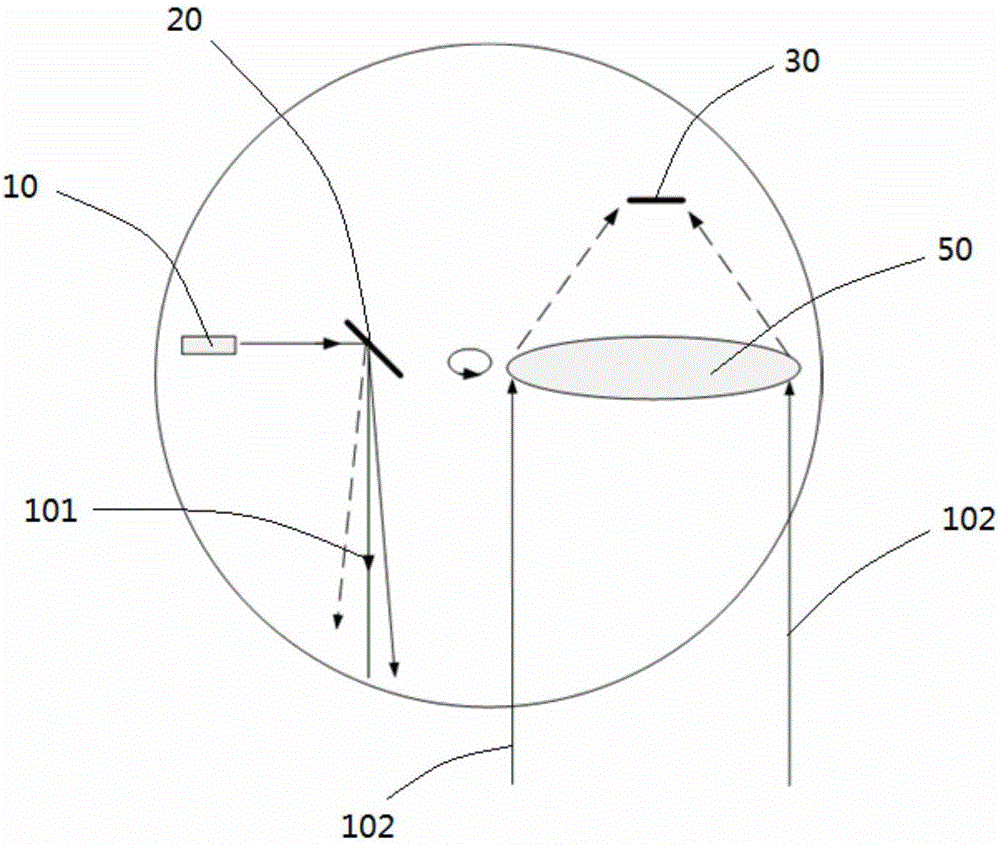
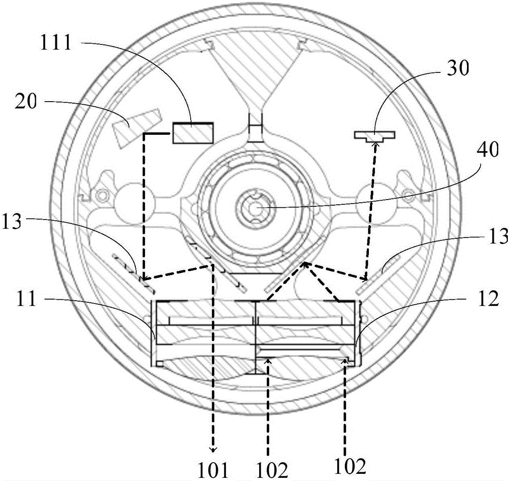
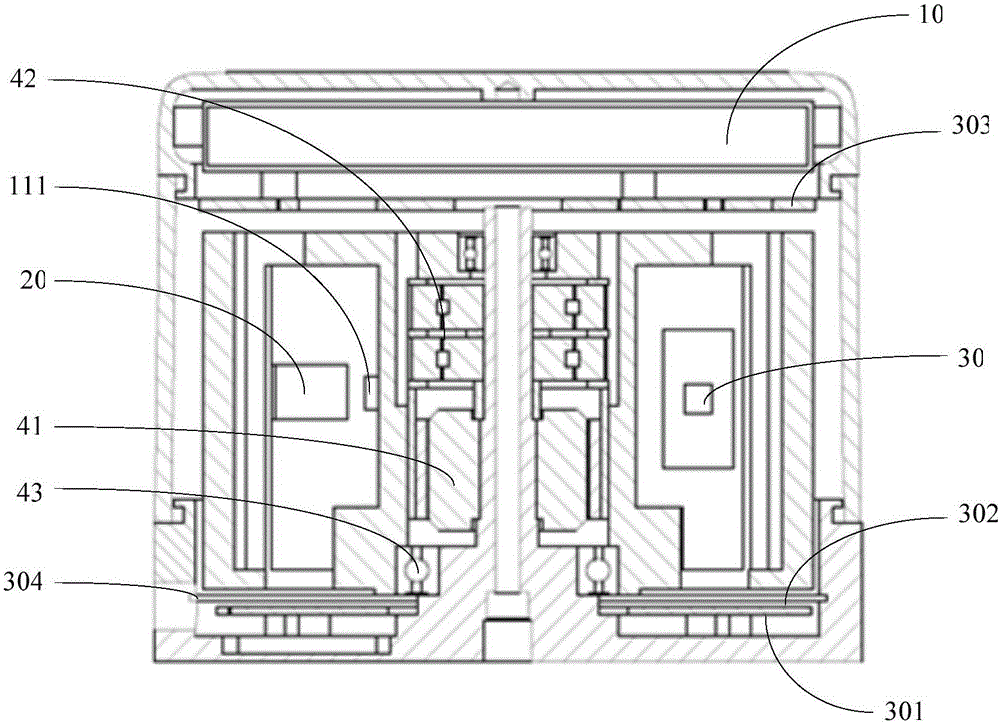
[0033] Preferred embodiments of the present invention are Figure 1~3 As shown, it at least includes: a laser 10 emitting an outgoing laser light 101; a MEMS (Micro-Electro-Mechanical System, Micro-Electro-Mechanical System) micromirror 20, refracting the outgoing laser light 101 and performing laser scanning on the target area according to a preset rotation angle The receiving detector 30 receives the reflected laser light 102 of the target reflector in the target area and converts it into an echo pulse signal; the signal processing module receives and processes the echo pulse signal to obtain the...


PUM


Abstract

The present invention relates to the technical field of radars and discloses a laser radar system based on MEMS micro mirror scanning. The laser scanning of a target area is carried out by using the outgoing laser emitted by an MEMS micro mirror reflection laser according to a preset specified rotation angle, a receiving detector receives the reflection laser of a target reflection object in a target area and converts the reflection laser into an echo pulse signal, and a signal processing module receives and processes the echo pulse signal so as to obtain the position information of the target reflection object. Therefore, the laser radar system has a high measurement frequency and low cost.

Description

technical field [0001] The invention relates to the technical field of radar, in particular to a laser radar system based on MEMS micromirror scanning. Background technique [0002] The current multi-line laser radar realizes multi-line scanning by multiple transmitting lasers and multiple receiving detectors, such as the laser radar VLP-16 of Verlodyne Company in the United States, which requires 16 lasers to transmit and receive, 16 transmitting circuits and receiving circuits. It is difficult to deal with, the timing algorithm is difficult to control, and this laser uses a laser diode, the maximum peak power of the laser is 75W, and when the measurement distance is 200m, if the target reflectivity is small, there will be no echo signal. [0003] In summary, there are obviously inconveniences and defects in the actual use of the prior art, so it is necessary to improve it. Contents of the invention [0004] In view of the above-mentioned defects, the object of the prese...

Claims


Application Information

Patent Timeline
IPC IPC(8): G01S17/08
CPCG01S17/08
Inventor 胡小波王勇刘颖
Owner LEISHEN INTELLIGENT SYST CO LTD
Why Eureka
Try Eureka