Positive logic enabling power-on control circuit of power supply module

A power module and positive logic technology, which is applied in the field of power module power-on control circuit, can solve problems such as complex control and circuit complexity, and achieve the effect of simple circuit structure and reduced circuit cost

Active Publication Date: 2017-05-31
SHANGHAI SPACEFLIGHT INST OF TT&C & TELECOMM
View PDF6 Cites 1 Cited by
  • Summary
  • Abstract
  • Description
  • Claims
  • Application Information

AI Technical Summary

Problems solved by technology

Positive logic enable power-on control is just the opposite of negative logic enable power-on control, and the control is relatively complicated
[0003] The existing power-on control circuit based on the positive logic of the power module often simply judges the presence or absence of one of the power supply voltages to control the power-on and shutdown of the other power supply, or monitors the voltage value of one of the power supplies, but it needs to be combined with a single-chip microcomputer , AD sampling and other chips, the circuit is more complicated

Method used


Image

  • Positive logic enabling power-on control circuit of power supply module
  • Positive logic enabling power-on control circuit of power supply module
  • Positive logic enabling power-on control circuit of power supply module

Examples


Embodiment Construction

[0028] In order to make the above objects, features and advantages of the present invention more comprehensible, specific implementations of the present invention will be described in detail below in conjunction with the accompanying drawings.

[0029] In the following description, numerous specific details are set forth in order to provide a thorough understanding of the present invention. However, the present invention can be implemented in many other ways different from those described here, and those skilled in the art can make similar extensions without violating the connotation of the present invention, so the present invention is not limited by the specific implementations disclosed below.

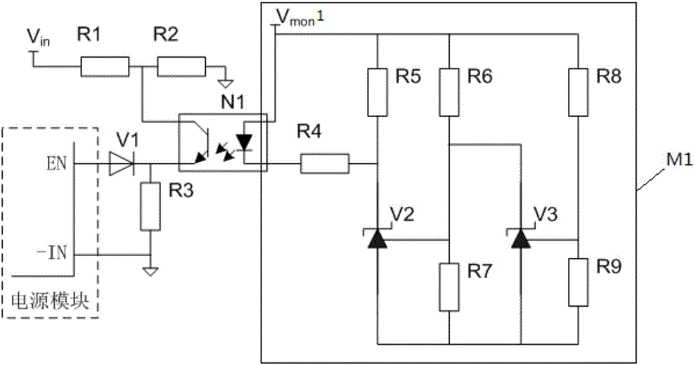
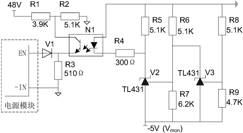
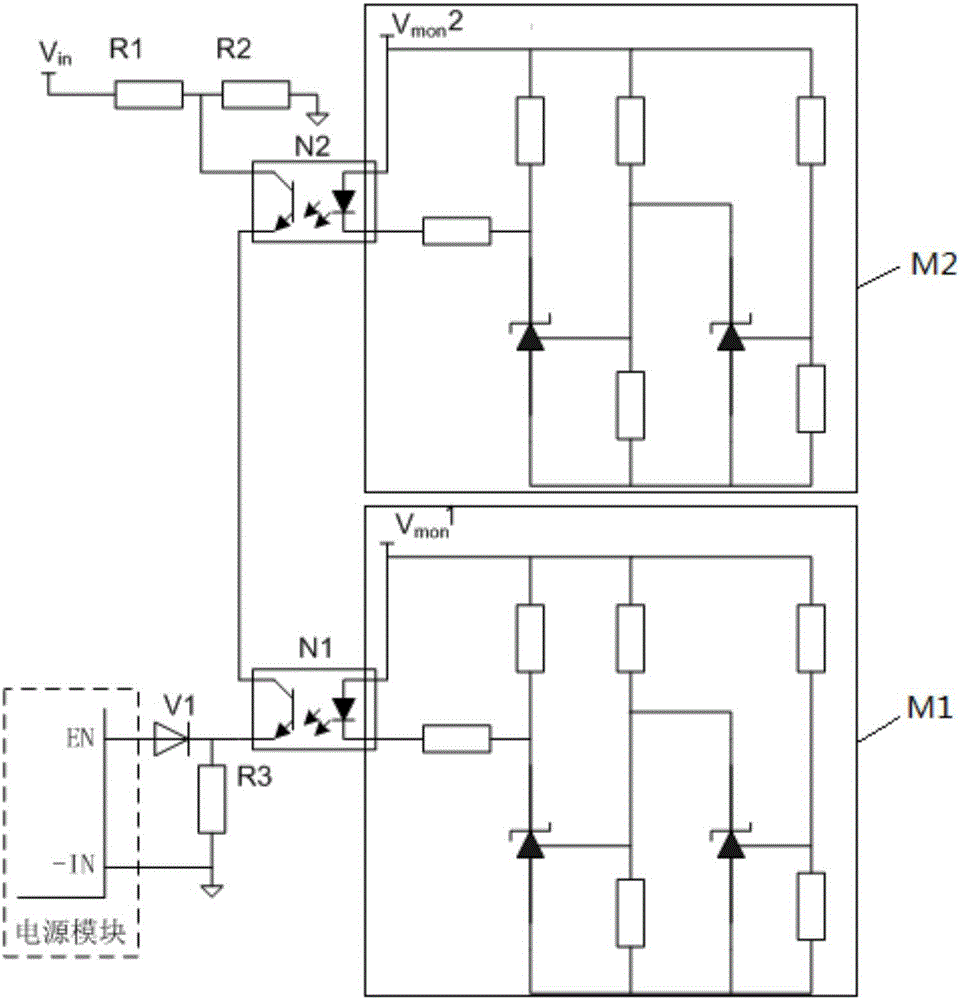
[0030] The positive logic enable power-on control circuit of the power module in the embodiment of the present invention includes: a diode circuit, and at least one level of control unit. The positive end of the diode circuit is connected to the enabling end of the power module, and...


PUM


Abstract

The invention provides a positive logic enabling power-on control circuit of a power supply module. The positive logic enabling power-on control circuit comprises a diode circuit, a photoelectric isolation coupler, and a zone conduction control circuit. The positive terminal of the diode circuit is connected with an enabling terminal of a power supply module and the negative terminal of the diode circuit is connected with an input negative terminal of the power supply module. A collector of a triode of the photoelectric isolation coupler receives an input voltage and an emitter of the triode is connected with the negative terminal of the diode circuit. The zone conduction control circuit receiving a monitoring voltage of a monitored power supply is used for controlling a light-emitting diode of the photoelectric isolation coupler to be in conduction when the monitoring voltage exceeds a lower limit voltage and does not exceed an upper limit voltage, so that the triode of the photoelectric isolation coupler is in conduction and thus the enabling terminal of the power supply module is disconnected with the input negative terminal and the power supply module outputs the voltage. When the monitoring voltage exceeds the upper limit voltage, the zone conduction control circuit controls the light-emitting diode of the photoelectric isolation coupler to be cut off, so that the triode of the photoelectric isolation coupler is cut off and thus the enabling terminal of the power supply module is connected with the input negative terminal and the power supply module does not output the voltage. Therefore, the load damage resulted from power-on operation can be prevented.

Description

technical field [0001] The invention relates to a power-on control circuit for a power module, in particular to a positive logic enable power-on control circuit for a power module. Background technique [0002] For some loads, multiple power supplies are required, and there are strict requirements on the power supply sequence of the multiple power supplies. For example, a power amplifier requires two voltages, the gate voltage and the drain voltage, and the drain voltage must be added only when the gate voltage is normal. The power supply module with enable function can be used to control the power-on sequence. The power supply module can be divided into positive logic and negative logic. Negative logic enable power-on control means that when the enable pin is suspended, the power module is closed and has no output When the enable pin is connected to the input negative terminal, the power module will output voltage when it is powered on, and the control is relatively simple...

Claims


Application Information

Patent Timeline
Patent Type & Authority Applications(China)
IPC IPC(8): G05B7/02
CPCG05B7/02
Inventor 许娟陈辉姚崇斌嵇玮玮肖辉董硕王正之
Owner SHANGHAI SPACEFLIGHT INST OF TT&C & TELECOMM
Why Eureka
Try Eureka