UWB Antennas and Antenna Arrays

An ultra-wideband antenna and array technology, which is applied to antenna arrays, individually powered antenna arrays, antennas, etc., can solve the problems of limited miniaturization of ultra-wideband antennas, increase the effective radiation area, widen the low-frequency bandwidth, and increase the antenna bandwidth. Effect

Active Publication Date: 2022-08-02
SHANGHAI AMPHENOL AIRWAVE COMM ELECTRONICS CO LTD
View PDF0 Cites 0 Cited by
  • Summary
  • Abstract
  • Description
  • Claims
  • Application Information

AI Technical Summary

Problems solved by technology

[0005] In view of the shortcomings of the prior art described above, the object of the present invention is to provide an ultra-wideband antenna and an antenna array, which are used to solve the problem of miniaturization of ultra-wideband antennas in the field of satellite communication and navigation and / or mobile communication in the prior art. limited issues

Method used


Image

  • UWB Antennas and Antenna Arrays
  • UWB Antennas and Antenna Arrays
  • UWB Antennas and Antenna Arrays

Examples


Embodiment 1

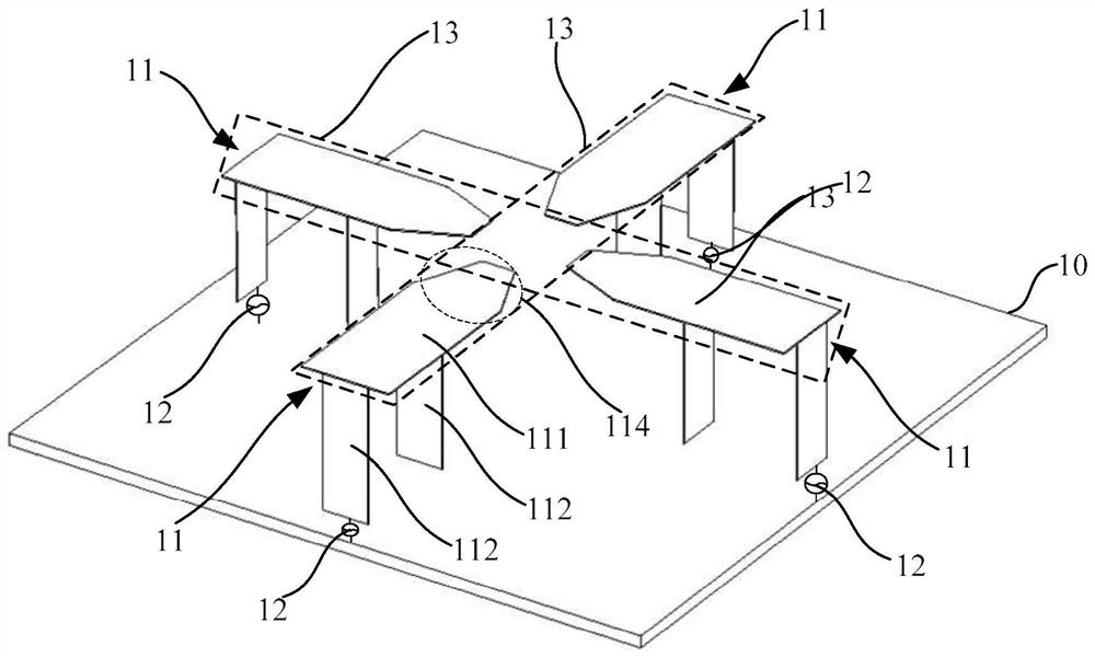
[0108] This embodiment can implement an ultra-wideband antenna with GNSS L1, L2 and SDARS functions. By setting the ultra-miniaturized wideband antenna in this embodiment, the GNSS L1 (1.56G-1.605G) frequency band, L2 (1.2G-1.26G) frequency band can be realized at the same time. ) frequency band right-hand circularly polarized wave antenna function and SDARS 2.32G ~ 2.45G frequency band left-hand circularly polarized wave receiving function. The integration degree and space utilization rate of the system are improved; at the same time, different from the traditional design method of using high-cost and high-dielectric-constant ceramics as the dielectric material for the traditional patch antenna, this embodiment adopts the same antenna size under the condition of keeping the same size. The low-cost, low-dielectric constant of 4 plastic material also meets the requirements of the low-frequency 1.2G frequency band, and indirectly realizes the miniaturization function.

[0109] l...

Embodiment 2

[0120] The ultra-wideband antenna of this embodiment is used for the ultra-wideband millimeter-wave antenna of the all-metal frame terminal user equipment. Nowadays, all-metal frame mobile phones have become the mainstream. The antenna array formed by the ultra-wideband antenna of this embodiment as a unit realizes the design of a 5G millimeter-wave array antenna in a metal frame environment. 42.5G ultra-wide frequency band requirements for dual polarization. like Figure 23 and Figure 24 As shown, the antenna also includes a metal wall 16 and a medium 18. The four sub-metal structural units 11 are located in a metal cavity structure 17 formed by the reference ground metal plate 10 and the metal wall 16. The metal wall 16 and the reference ground metal plate Electrical connection or non-electrical connection between 10, the material of the medium 18 is PTFE with a low dielectric constant of 2 and a tangent loss of 0.003, the size of the medium 18 is 4.5mm*4.5mm*1.1mm, fille...


PUM


Abstract

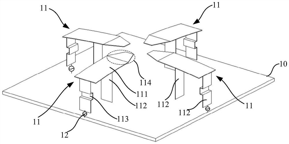
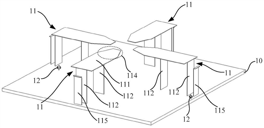
The present invention provides an ultra-wideband antenna and an antenna array, comprising: a reference ground metal plate, four identical sub-metal structural units arranged thereon and arranged at equal intervals of 90° in the circumferential direction, and four feeding structures; the sub-metal structure The unit includes: a first metal structure extending in a horizontal direction, two second metal structures extending in a vertical direction, two second metal structures are directly connected to the first metal structure, and one second metal structure The metal structure is connected to the reference ground metal plate, and a feeding structure is added between the other second metal structure and the reference ground metal plate. Four sub-metallic structural units arranged at equal intervals of 90° in the circumferential direction and multiple grounding points are added, and by applying a differential feed with a phase difference of 180° to the two oppositely-arranged sub-metallic structural units, the four sub-metal structural units are simultaneously The metal structural units have a coupling effect to form an ultra-wideband antenna; in addition, the radiation gain and the antenna bandwidth are increased, and the miniaturization effect is achieved at the same time.

Description

technical field [0001] The invention relates to the design field of ultra-wideband antenna structures, in particular to an ultra-wideband antenna and an antenna array. Background technique [0002] With the continuous expansion of communication frequency bands and the improvement of the integration of various functional modules in the system, the demand for miniaturized broadband antennas is getting higher and higher, and the design is also becoming more and more challenging. [0003] For example, in the field of satellite communication and navigation, the GNSS system and the SDARS system, both of which communicate through circularly polarized waves, are often discussed together. GNSS systems mainly include well-known navigation systems such as GPS in the United States, Galileo in Europe, GLONASS in Russia and Beidou system in China. wave (RHCP). The SDARS system is the abbreviation of satellite digital audio broadcasting service, its frequency band is 2.32G-2.345G, and th...

Claims


Application Information

Patent Timeline
Patent Type & Authority Patents(China)
IPC IPC(8): H01Q1/36H01Q1/50H01Q1/48H01Q21/00H01Q21/20
CPCH01Q1/36H01Q1/50H01Q1/48H01Q21/0006H01Q21/20
Inventor 商进杨杰钧
Owner SHANGHAI AMPHENOL AIRWAVE COMM ELECTRONICS CO LTD
Why Eureka
Try Eureka