
Real-time wireless measurement and control system for engineering vehicle state

A technology of engineering vehicles and measurement and control systems, applied in the field of remote real-time measurement and control systems of engineering vehicles, can solve the problems of difficult to meet the requirements of instruments and meters, high work intensity, lack of power supply for debugging equipment, etc., to improve the debugging working environment and function changes Simple adjustment, convenient remote real-time monitoring effect

Inactive Publication Date: 2017-05-31
上海申赛机电控制技术有限公司
View PDF7 Cites 14 Cited by
  • Summary
  • Abstract
  • Description
  • Claims
  • Application Information

AI Technical Summary

Problems solved by technology

[0002] With the improvement and development of the automation and intelligence of engineering vehicles in my country, more and more vehicle status parameters and operating parameters need to be set that need to be collected and displayed in real time in the process of debugging, operation and fault diagnosis. It is difficult to meet the requirements, the development and application of intelligent instruments and meters is an urgent need in the future
During the debugging process of the automatic shift controller (TCU) of engineering vehicles, it is extremely inconvenient to use traditional instruments to observe and record the vehicle status, such as the small space in the cab, inconvenient signal wiring, lack of power supply for debugging equipment, strong vibration and noise, and working environment. harsh, hard work

Method used


Image

  • Real-time wireless measurement and control system for engineering vehicle state
  • Real-time wireless measurement and control system for engineering vehicle state

Examples


Embodiment Construction

[0020] Exemplary embodiments of the present disclosure will be described in more detail below with reference to the accompanying drawings. Although exemplary embodiments of the present disclosure are shown in the drawings, it should be understood that the present disclosure may be embodied in various forms and should not be limited by the embodiments set forth herein. Rather, these embodiments are provided for more thorough understanding of the present disclosure and to fully convey the scope of the present disclosure to those skilled in the art.

[0021] In describing the present invention, it should be understood that the terms "longitudinal", "transverse", "upper", "lower", "front", "rear", "left", "right", "vertical", The orientations or positional relationships indicated by "horizontal", "top", "bottom", "inner", "outer", etc. are based on the orientations or positional relationships shown in the drawings, and are only for the convenience of describing the present inventi...


PUM


Abstract

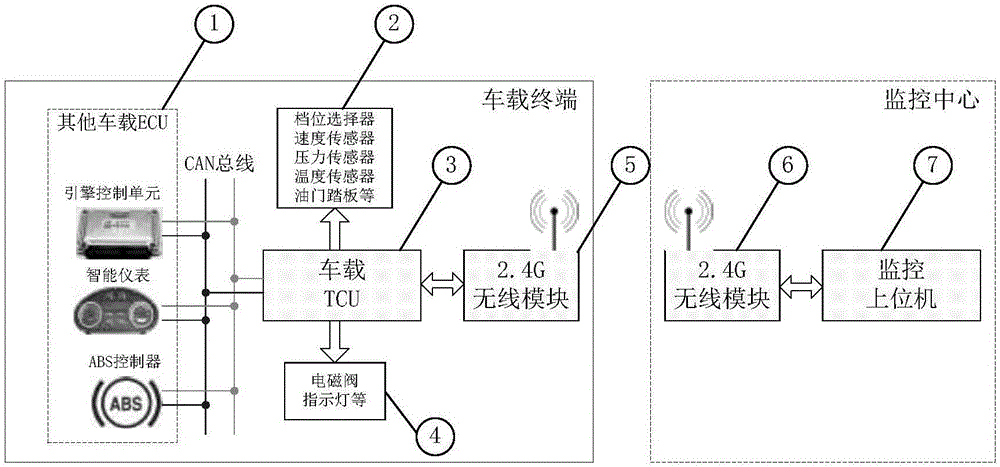
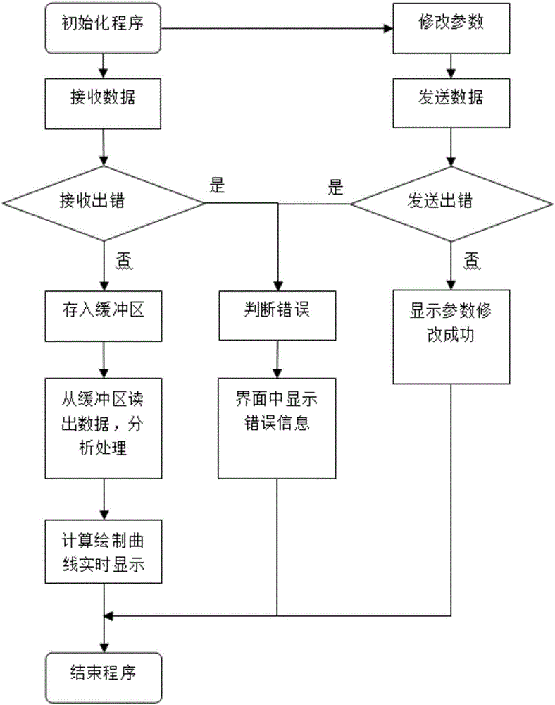
Disclosed is a real-time wireless measurement and control system for engineering vehicle state. The system comprises two parts of a vehicle terminal and a remote supervising center. A remote communication is made by using a 2.4 G point-to-point wireless transmission module with a power amplifier, achieving on-site data collecting to the engineering vehicle, motion controlling of the vehicle operating, real-time remote monitoring, status displaying, parameter setting, record keeping, and further back-end data processing. The debugging is not restricted by the on-site space and material conditions of the engineering vehicles. Using the 2.4 G wireless module with a power amplifier can achieve the data transmission without any barriers within 1 km. All the data detected directly or indirectly of the whole vehicle can be real-time monitored and displayed. The system has the function of historical data record keeping, and provides the possibility for further analysis and diagnosis. Provide interfaces based on needs. Authorize users personalization to set certain operating parameters. In this way, the debugging efficiency is improved and the debugging environment is improved greatly. The upper computer monitoring software develops using a Labview, making it simple and convenient to change and adjust the function.

Description

technical field [0001] The invention relates to a remote real-time measurement and control system for the status of engineering vehicles, which is used for remote real-time monitoring of the running status of the vehicles during the commissioning and testing stages of the engineering vehicle switchboard, in particular to a real-time wireless measurement and control system for the status of engineering vehicles. Background technique [0002] With the improvement and development of the automation and intelligence of engineering vehicles in my country, more and more vehicle status parameters and operating parameters need to be set that need to be collected and displayed in real time in the process of debugging, operation and fault diagnosis. It is difficult to meet the requirements, and the development and application of intelligent instruments and meters is an urgent need in the future. During the debugging process of the automatic shift controller (TCU) of engineering vehicles...

Claims


Application Information

Patent Timeline
Patent Type & Authority Applications(China)
IPC IPC(8): G05B19/048G08C17/02
CPCG05B19/048G08C17/02
Inventor 关景泰傅佳浩
Owner 上海申赛机电控制技术有限公司
Learn More