Vision based steady object tracking control system and method for rotor UAV (unmanned aerial vehicle)

A technology for unmanned and stable tracking of rotors, applied in the field of visual tracking, can solve problems such as the inability of rotorcraft to track moving targets stably, achieve smooth tracking flight process, ensure effect and accuracy, and avoid the effect of oscillation

Active Publication Date: 2017-05-31
NANJING UNIV OF AERONAUTICS & ASTRONAUTICS
View PDF5 Cites 40 Cited by
  • Summary
  • Abstract
  • Description
  • Claims
  • Application Information

AI Technical Summary

Problems solved by technology

[0006] The technical problem to be solved by the present invention is to overcome the deficiencies of the prior art and provide a vision-based control system and method for a rotor UAV to stably track a moving target, and use an airborne visual navigation modul

Method used


Image

  • Vision based steady object tracking control system and method for rotor UAV (unmanned aerial vehicle)
  • Vision based steady object tracking control system and method for rotor UAV (unmanned aerial vehicle)
  • Vision based steady object tracking control system and method for rotor UAV (unmanned aerial vehicle)

Examples


Embodiment Construction

[0051] Below in conjunction with accompanying drawing, technical scheme of the present invention is described in further detail:

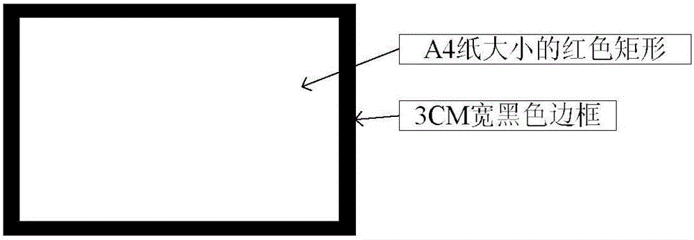
[0052] The present invention is designed as figure 1 The target feature flags are shown. The main body of the target feature mark is a red rectangle the size of A4 paper, its length and width are 297mm and 210mm respectively, the value corresponding to the RGB color is (255,0,0), and the periphery is a black border with a width of 3cm.

[0053] In the rotor UAV control system of the present invention, the flight controller is used as the "brain" of the rotor UAV, and is supplemented by the visual navigation module, sensor part, wireless communication unit, power unit and power supply module to complete tasks such as the stable visual tracking of moving targets by rotor UAVs.

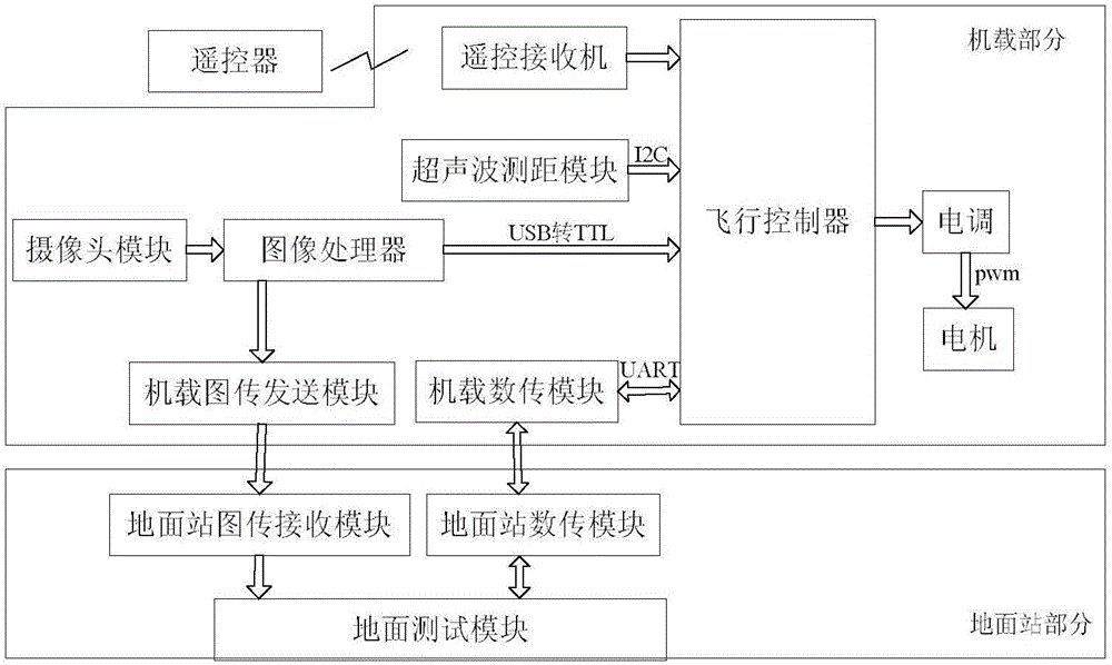
[0054] like figure 2 As shown, a vision-based control system for rotor UAVs to stably track moving targets mainly includes an airborne part and a ground station part. , ...


PUM


Abstract

The invention discloses a vision based steady object tracking control system for a rotor UAV (unmanned aerial vehicle). The system comprises an airborne part, wherein the airborne part comprises a flight control unit of the rotor UAV, an ultrasonic ranging module and a visual navigation module; the visual navigation module comprises an image processor, a camera module and a two-axis brushless pan-tilt unit which is fixed under the rotor UAV; the camera module and the ultrasonic ranging module are both fixed on the two-axis brushless pan-tilt unit, and a lens of the camera module and the ultrasonic ranging module are both parallel to the horizontal plane. The invention further discloses a vision based steady object tracking control method for the rotor UAV. The airborne visual navigation module is used for automatically detecting a target characteristic indication and solving the practical relative error distance between the rotor UAV and a target object, and the problem that the rotor UAV cannot steadily track a moving object under the condition that the target object is shielded is particularly solved.

Description

technical field [0001] The invention relates to the technical field of vision tracking, in particular to a control system and method for a vision-based rotor UAV to stably track a moving target. Background technique [0002] In recent years, rotor drones have frequently appeared in the public's field of vision. For example, the traffic department uses rotor drones to check road conditions in real time, and secretly captures illegal driving behavior on expressways; large power stations use rotor drones to monitor solar power. The rescue team used the rotor drone to detect the disaster situation and delivered necessary materials such as food and medicine to the affected people in time. There are many other applications like this. It can be seen that rotor UAVs play a very important role in civilian, rescue and even military applications. However, the above-mentioned applications are almost all in the case of strong outdoor GPS signals, using the onboard GPS to provide real-ti...

Claims


Application Information

Patent Timeline
IPC IPC(8): G05D1/12
CPCG05D1/12Y02T10/40
Inventor 单一刘春生孙景亮李蔚蓝
Owner NANJING UNIV OF AERONAUTICS & ASTRONAUTICS
Why Eureka
Try Eureka