Detonator code identification device

A coding identification and detonator technology, which is applied in electromagnetic radiation induction, instruments, induction recording carriers, etc., can solve the problems of heavy equipment, complex structure, and inability to work continuously, so as to simplify the identification operation of detonators, reduce production costs, and simplify the process. Effect

Inactive Publication Date: 2017-05-31
GUANGZHOU BENAN INFORMATION TECH CO LTD
View PDF3 Cites 1 Cited by
  • Summary
  • Abstract
  • Description
  • Claims
  • Application Information

AI Technical Summary

Problems solved by technology

[0003] At present, a detonator code recognition device of a detonator automatic recognition machine with a complex structure is used, which uses two synchronous pulleys and two shafts. Due to the problem of wiring, the image acquisition device can only rotate 370-380 degrees. After the completion, the image acquisition device needs to be reset, the operation is cumbersome, the structure is complicated, and it cannot work continuously. At the same time, because many times it will work in the field, the current equipment is too heavy and difficult to carry, which causes some inconvenience. Therefore, it is necessary to find some more convenient way of working

Method used


Image

  • Detonator code identification device

Examples


Embodiment Construction

[0024] Embodiments of the present invention are described in detail below, examples of which are shown in the accompanying drawings, wherein the same or similar reference numerals represent the same or similar elements or elements with the same or similar functions; The examples are exemplary and are intended to explain the present invention, but should not be construed as limiting the present invention.

[0025] The detonator code recognition device according to the embodiment of the present invention will be described in detail below with reference to the accompanying drawings.

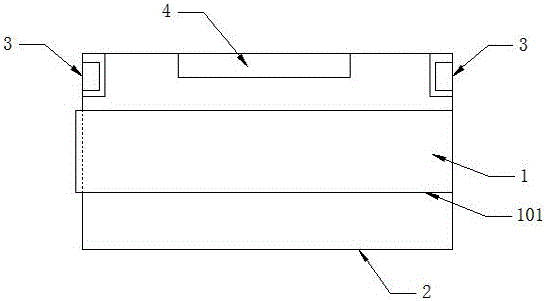
[0026] Such as figure 1 As shown, the detonator code recognition device according to the embodiment of the present invention includes: a detonator 1 , a detonator casing 101 , a placement cavity 2 , a light source 3 and an identification component 4 .

[0027] Such as figure 1 As shown, the detonator code identification device according to the embodiment of the present invention includes: a light ...


PUM


Abstract

The present invention discloses a detonator code identification device. The detonator code identification device comprises light sources and an identification unit. Each light source is located in a location where dazzling light cannot be formed when identification light emitted from the light source irradiates on a detonator and enters the identification unit after being reflected, and the identification unit is mounted on a location where the code on the detonator can be identified. According to the detonator code identification device disclosed by the invention, the condition that the identification of the detonator code without considering a routing mode of scanning parts can be achieved, the detonator code identification device is simple in structure, convenient in operation, and has greater advantages.

Description

technical field [0001] The invention relates to the field of detonator management, in particular to a detonator code identification device. Background technique [0002] The public security department stipulates that the use of detonators must be clearly registered and recorded, indicating the custodian, issuer, recipient, use item, use location, quantity, type, waste, etc. All items are indispensable, and there is a strict use system; Relevant departments of the state strictly control the circulation process of dangerous goods such as detonators, and require that the management of detonators in actual production be more and more detailed. It seems that the production and use of detonators will be included in the automatic management of computers. The application of recognition to management is also becoming more and more urgent. [0003] At present, a detonator code recognition device of a detonator automatic recognition machine with a complex structure is used, which uses...

Claims


Application Information

Patent Timeline
Patent Type & Authority Applications(China)
IPC IPC(8): G06K7/14
CPCG06K7/146
Inventor 周安法王沛玉
Owner GUANGZHOU BENAN INFORMATION TECH CO LTD
Why Eureka
Try Eureka