Tension detection control device for center-based stranding machine

A control device and tension detection technology, which is applied in the direction of cable/conductor manufacturing, electrical components, circuits, etc., can solve problems such as easy loosening, uneven finished products, and arching, and achieve the effect of improving stranding quality and releasing tension evenly and stably

Inactive Publication Date: 2017-05-31
安徽长江精工装备科技有限公司
View PDF7 Cites 4 Cited by
  • Summary
  • Abstract
  • Description
  • Claims
  • Application Information

AI Technical Summary

Problems solved by technology

In the stranding process, mechanical friction or electrical setting parameters are usually used to control the tension of a single wire conductor. The disadvantage is that during the operation of the equipment, as the wire conductors stored in the pay-off reel change from a full reel to a shallow reel , the tension cannot be detected in real time and the stability of the pay-off tension of the wire conductor in the reel can be adjusted, which may easily cause wire breakage during the stranding process and the finished product after stranding is not smooth, arched, and easy to loose, and sometimes the cable conductor line Core DC resistance unqualified and other quality defects
If it is not dealt with or improved in time, it will seriously affect the safe operation of the cable
With the rapid development of power cables in my country, the quality requirements for large-section conductive core products have been improved, and strict requirements are required for the release tension of the conductive core to be uniform and stable. The traditional outlet tension device has been unable to meet the equipment requirements.

Method used


Image

  • Tension detection control device for center-based stranding machine
  • Tension detection control device for center-based stranding machine
  • Tension detection control device for center-based stranding machine

Examples


Embodiment Construction

[0016] In order to make the present invention clearer, the device will be described in detail below in conjunction with the accompanying drawings. The specific embodiments described here are only used to explain the present invention, and are not intended to limit the present invention.

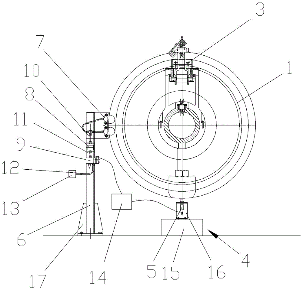
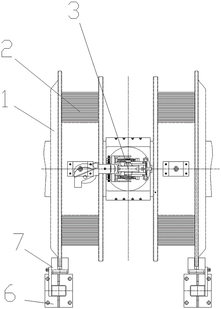
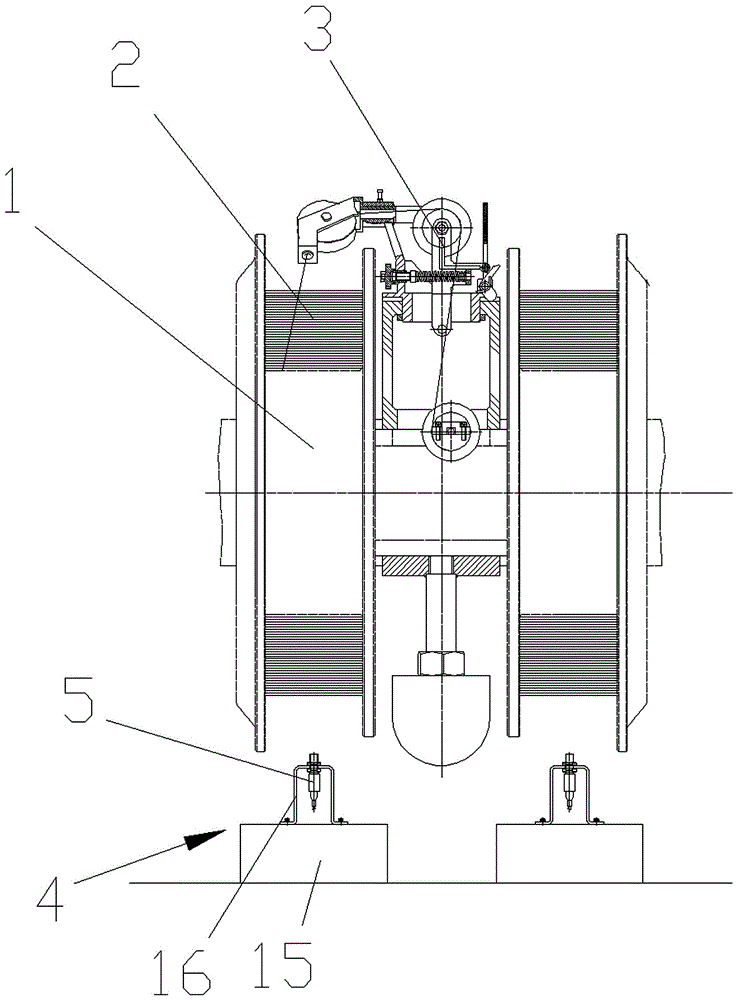
[0017] Such as figure 1 , figure 2 and image 3 As shown, a tension detection control device for a central stranding machine provided by the present invention includes a pay-off reel 1 on which wire cores 2 are wound, and on the pay-off reel 1 is also provided with wire The pay-off device 3 for the core 2 pay-off, the structures and connection methods of the pay-off reel 1, the wire core 2 and the pay-off device 3 are all prior art.

[0018] Directly below the pay-off reel 1 is provided with an inductor support 4, the inductor support 4 includes a fixed block 15, and the upper side of the fixed block 15 is connected and fixed with a U-shaped support plate 16, and the opening of the U-shape...


PUM


Abstract

The invention relates to a tension detection control device for a center-based stranding machine, comprising a pay-off spool (1). A cable core (2) is twined and connected on the pay-off spool, a range sensor (5) that is in induction fit with the cable core is arranged below the pay-off spool, one side of the pay-off spool is provided with a brake (7), a proportional pressure valve (8) and a solenoid valve (9) which are mounted through a brake support (6) and connected by a pipeline, and the solenoid valve is connected with an air source (12) through a third pipeline (12); and the tension detection control device further comprises a control device (14) connected with the range sensor and the solenoid valve. The tension detection control device has the advantages that the device is used for detecting the match degree of the change, from a full plate to a shallow plate, of a wire conductor stored in the pay-off spool and the line outgoing speed of a complete machine, matches up with an air pressure disc brake through an inductor detection feedback mode in the process of releasing the conductive cable core, and automatically adjusts the stability of line releasing tension of the wire conductor stored in the pay-off spool, so that the cable releasing tension is guaranteed to be uniform and stable, and the cable stranding quality is improved.

Description

technical field [0001] The invention relates to the technical field of component parts of a stranding machine, in particular to a tension detection control device for a central stranding machine. Background technique [0002] In the process of twisting a plurality of copper wires or aluminum single wires with smaller diameters into larger cross-section conductive cores according to certain rules by using a central twisting machine, according to the requirements of the twisting process, the number of different coils can be placed on the stranding body. Use in any combination. In the stranding process, mechanical friction or electrical setting parameters are usually used to control the tension of a single wire conductor. The disadvantage is that during the operation of the equipment, as the wire conductors stored in the pay-off reel change from a full reel to a shallow reel , the tension cannot be detected in real time and the stability of the pay-off tension of the wire cond...

Claims


Application Information

Patent Timeline
Patent Type & Authority Applications(China)
IPC IPC(8): H01B13/02
CPCH01B13/0207
Inventor 邵荣军孙厚明付磊吴建军
Owner 安徽长江精工装备科技有限公司
Why Eureka
Try Eureka