Prefabricated cable trench applied to subsidence areas

A prefabricated assembly and cable trench technology, which is applied in ground cable installation, cable installation and other directions, can solve the problems of high construction cost, high maintenance cost and high construction cost, and achieve the effect of improving production accuracy and high maintenance cost.

Active Publication Date: 2017-05-31
SHANGHAI ELECTRIC POWER DESIGN INST
View PDF5 Cites 10 Cited by
  • Summary
  • Abstract
  • Description
  • Claims
  • Application Information

AI Technical Summary

Problems solved by technology

[0002] At present, the cable trenches in my country's power transmission and transformation projects generally adopt two forms of cast-in-place reinforced concrete and brickwork. The construction period of on-site pouring or masonry is long, and the environmental impact is great. In winter construction, centralized maintenance cannot be performed, and the cost of maintenance according to length is high.
[0003] However, the cable trench made in sections by ordinary factories cannot overcome the difference in settlement between the sections. When the staggered platform is large, the stress on the edge of the pipe section is concentrated, and the local extrusion causes cracks. The waterproof measures between the two sections are damaged and cause water leakage. It is used in subsidence areas, areas with large differences in topography and geology, or areas with large cumulative settlement within the design period
[0004] Therefore, there is an urgent need for a prefabricated assembly that can overcome the high construction cost, long construction period, high maintenance cost, and large environmental impact of traditional cast-in-place reinforced concrete or brick cable trenches; it can adopt mechanized production, improve manufacturing precision, and be economical and environmentally friendly. type cable trench

Method used


Image

  • Prefabricated cable trench applied to subsidence areas
  • Prefabricated cable trench applied to subsidence areas
  • Prefabricated cable trench applied to subsidence areas

Examples


Embodiment

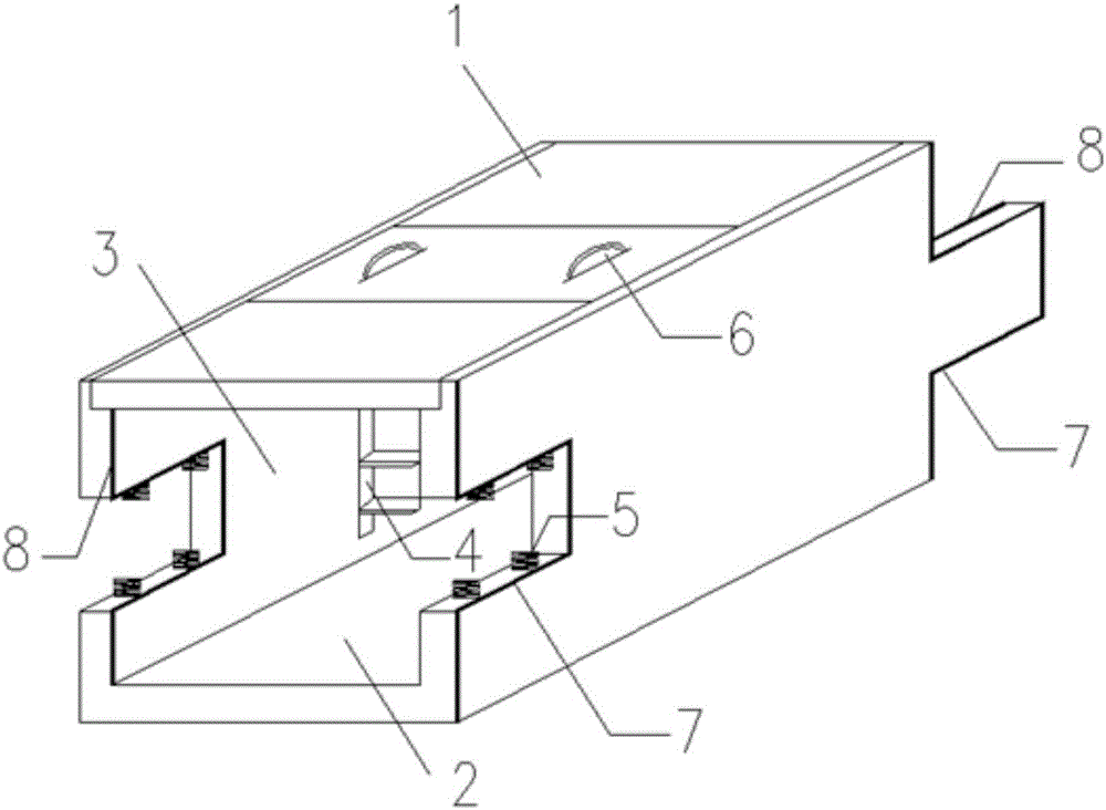
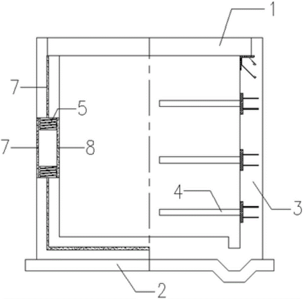
[0030] like figure 1 As shown, the prefabricated cable trench used in the subsidence area; the cable trench includes several pipe joint units, and each pipe joint unit includes a top plate 1, two side walls 2, and a bottom plate 3.

[0031] Wherein, the two sides of the top plate 1 are respectively connected to the upper sides of the two side walls 2, and the two sides of the bottom plate 3 are respectively connected to the lower sides of the two side walls 2, forming a tubular structure with two ends open.

[0032] The middle part of one end of the side wall 2 is provided with a protruding part, and the middle part of the other end is provided with a concave part, and the position and shape of the concave part and the protruding part correspond to each other.

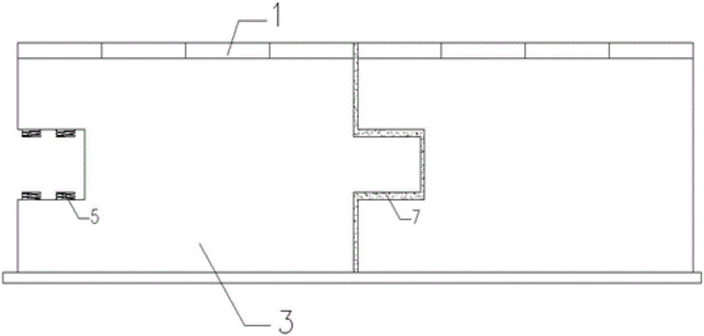
[0033] like image 3 As shown, every two adjacent pipe unit units are detachably connected by opposing inner concave parts and convex parts.

[0034] like figure 1 and figure 2 As shown, in some embodiments, the w...


PUM


Abstract

The invention discloses a prefabricated cable trench applied to subsidence areas. The cable trench comprises a plurality of pipe joint units. Each of the pipe joint units comprises a top plate, two side walls and a base plate, wherein two side edges of the top plate are connected with upper edges of the two side walls, two side edges of the base plate are connected with lower edges of the two side walls, and then a pipe-shaped structure with two ends open is formed; a bulgy portion is arranged in the middle of one end of each of the side walls while concave portions are arranged in the middles of other ends thereof, and the concave portions and the bulgy portions are corresponding in position and shape respectively; every two adjacent pipe joint units are connected detachably through the concave portions and the opposite bulgy portions. The prefabricated cable trench applied to the subsidence areas has the advantages that disadvantages including high construction and maintenance costs, long construction time and severe environmental impacts of a traditional cast-in-place reinforced concrete or bricked cable trench can be overcome, and the economic and environment-friendly prefabricated cable trench high in production precision can be produced mechanically.

Description

technical field [0001] The invention relates to the technical field of cable trenches, in particular to a prefabricated cable trench suitable for subsidence areas. Background technique [0002] At present, the cable trenches in power transmission and transformation projects in my country generally adopt two forms of cast-in-place reinforced concrete and brickwork. The construction period of on-site pouring or masonry is long, and the environmental impact is great. Centralized maintenance cannot be performed during winter construction, and the cost of maintenance according to length is high. [0003] However, the cable trench made in sections by ordinary factories cannot overcome the difference in settlement between the sections. When the staggered platform is large, the stress on the edge of the pipe section is concentrated, and the local extrusion causes cracks. The waterproof measures between the two sections are damaged and cause water leakage. It is used in subsidence ar...

Claims


Application Information

Patent Timeline
Patent Type & Authority Applications(China)
IPC IPC(8): H02G9/02
CPCH02G9/02
Inventor 任辰马晓元
Owner SHANGHAI ELECTRIC POWER DESIGN INST
Why Eureka
Try Eureka