Over-current protection and anti-latch-up circuit
A latch circuit and overcurrent protection technology, applied in the electronic field, can solve problems such as increased latch sensitivity, affecting normal operation of circuits, and increased risk of failure
- Summary
- Abstract
- Description
- Claims
- Application Information
AI Technical Summary
Problems solved by technology
Method used
Image

Examples
Embodiment Construction
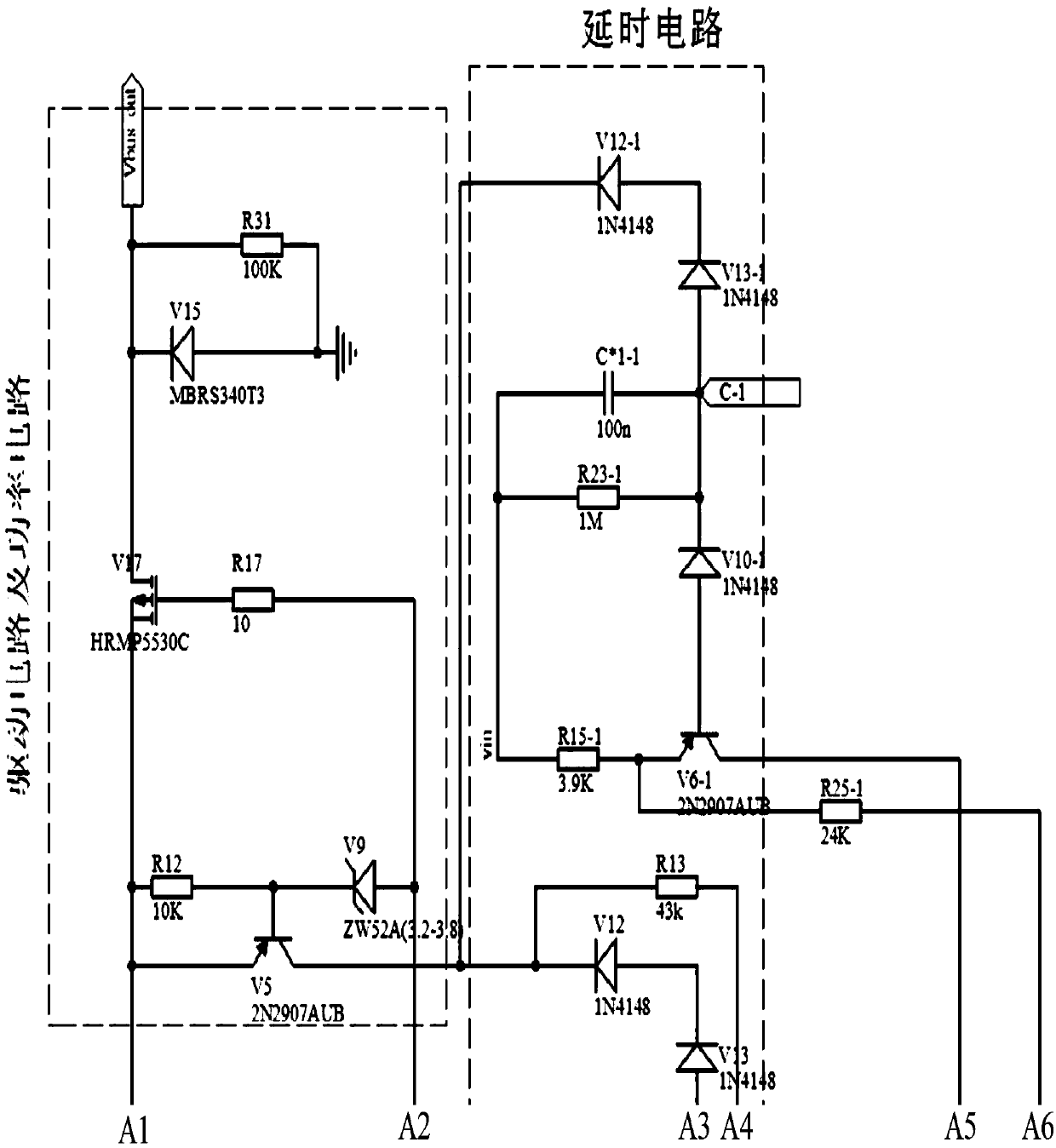
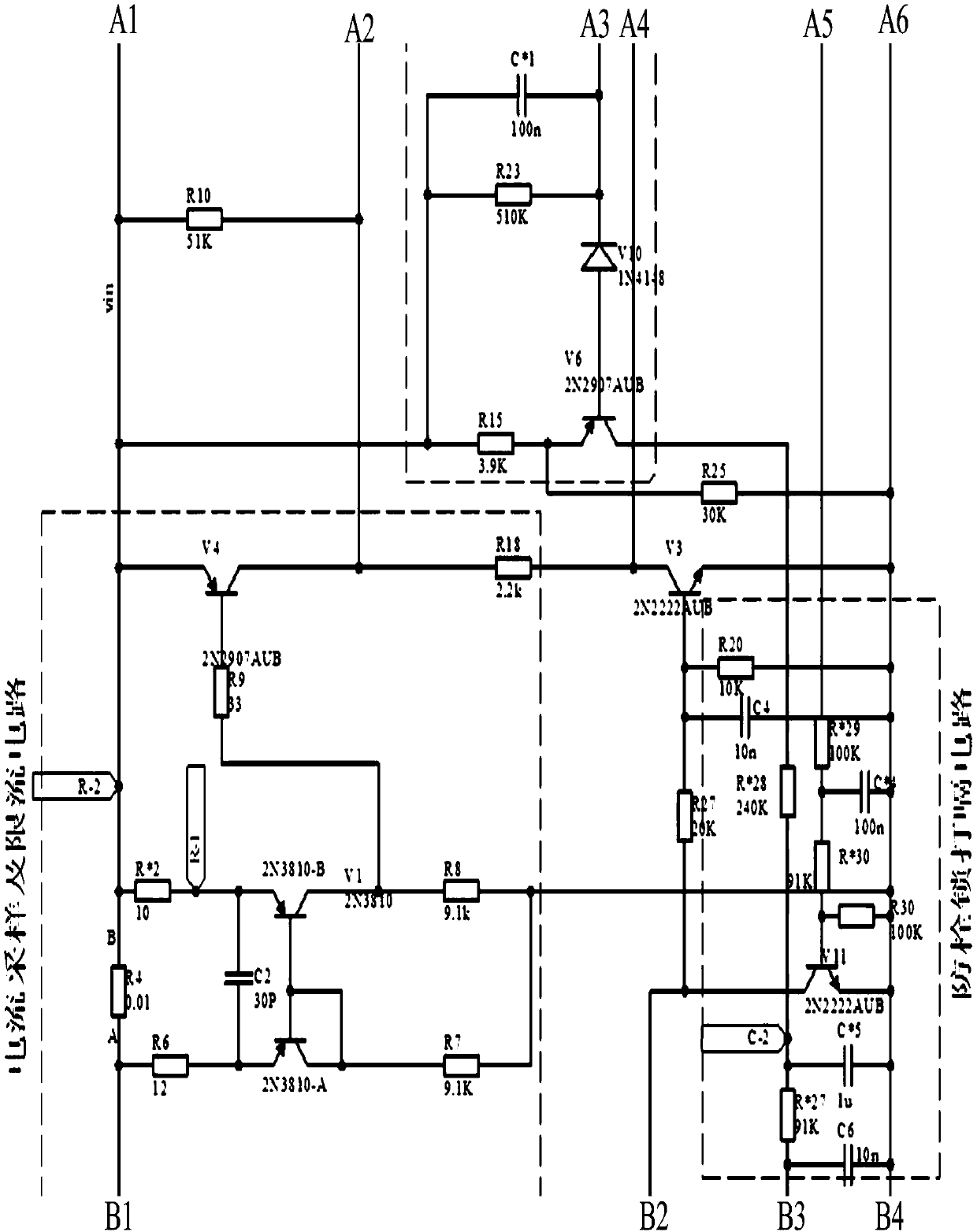
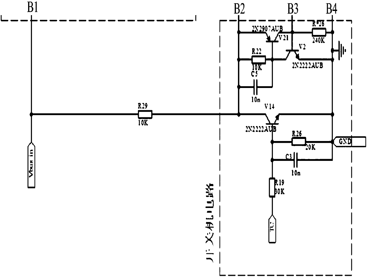
[0020] Such as Figure 1-3 As shown, the present invention discloses an overcurrent protection and anti-latch circuit, including a switch circuit, a current sampling and current limiting circuit, an anti-latch hiccup circuit, a drive circuit and a power circuit. The overcurrent protection and anti-latch circuit The circuit also includes a resistor R29 and a transistor V3. The current sampling and current limiting circuit includes a resistor R4, a resistor R6, a capacitor C2, a pair of tubes V1, a resistor R7, a resistor R8, a resistor R*2, a resistor R9, a transistor V4, and a resistor R18. , the input end of the overcurrent protection and anti-latch circuit is respectively connected to one end of the resistor R29, one end of the resistor R6, and the A end of the resistor R4, and the B end of the resistor R4 is connected to one end of the resistor R*2, and the R * The other end of 2 is connected to the emitter of 2N3810-B of V1, the other end of the resistor R6 is connected to...
PUM
 Abstract
Description
Claims
Application Information
 - R&D
- Intellectual Property
- Life Sciences
- Materials
- Tech Scout
- Unparalleled Data Quality
- Higher Quality Content
- 60% Fewer Hallucinations
Browse by: Latest US Patents, China's latest patents, Technical Efficacy Thesaurus, Application Domain, Technology Topic, Popular Technical Reports.
© 2025 PatSnap. All rights reserved.Legal|Privacy policy|Modern Slavery Act Transparency Statement|Sitemap|About US| Contact US: help@patsnap.com