DC micro-grid system and control method

A technology of DC microgrid and microgrid, applied in the field of microgrid, can solve problems such as no solution proposed

Inactive Publication Date: 2017-05-31
GREE ELECTRIC APPLIANCES INC
View PDF2 Cites 7 Cited by
  • Summary
  • Abstract
  • Description
  • Claims
  • Application Information

AI Technical Summary

Problems solved by technology

[0004] For the problem of how to improve the stability of the DC bus volta

Method used


Image

  • DC micro-grid system and control method
  • DC micro-grid system and control method
  • DC micro-grid system and control method

Examples


Embodiment 1

[0040] The DC microgrid system provided by the present invention will be described below with reference to the accompanying drawings.

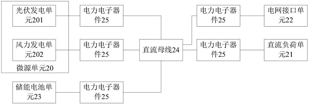
[0041] figure 1 An optional structural block diagram of a DC microgrid system showing an embodiment of the present invention, such as figure 1 As shown, the DC micro-grid system includes: a micro-source unit 20 composed of a photovoltaic power generation unit 201 and a wind power generation unit 202, a DC load unit 21, a grid interface unit 22, an energy storage battery unit 23, and a DC bus 24, wherein the micro-source The unit 20, the DC load unit 21, the grid interface unit 22, and the energy storage battery unit 23 are connected to the DC bus 24 through the power electronic device 25, and the energy exchange is realized through the DC bus 24. 21. The respective controllers of the grid interface unit 22, the energy storage battery unit 23 and the micro-grid central controller MGCC are jointly controlled, and the micro-grid central controll...

Embodiment 2

[0048] Based on the DC microgrid system provided in Embodiment 1 above, an optional embodiment 2 of the present invention also provides a control method for a DC microgrid system. The DC microgrid system includes: a photovoltaic power generation unit and a wind power generation unit The micro-source unit, the DC load unit, the grid interface unit, the energy storage battery unit, and the DC bus, wherein the micro-source unit, the DC load unit, the grid interface unit, and the energy storage battery are connected to the DC bus through power electronic devices, and the methods include: Each unit of the DC microgrid system is jointly controlled by the respective controllers of the micro-source unit, DC load unit, grid interface unit, energy storage battery unit, and system microgrid central controller to realize energy exchange through the DC bus. Among them, the microgrid central controller The MGCC is the upper-level controller relative to the respective controllers.

[0049] F...


PUM


Abstract

The invention discloses a DC micro-grid system and a control method, wherein, the system comprises micro-source module composed of photovoltaic power generation module and wind power generation module, DC carrier module, grid interface module, energy storage battery module and DC bus, wherein, the micro-source module, DC carrier module, grid interface module, the energy storage battery module is connected with DC bus through power electronic device and realizes energy exchange through DC bus, the DC micro-grid is controlled commonly by the separate controller of the micro-source module, the DC carrier module, the grid interface module, the energy storage battery module and micro-grid central controller, the micro-grid central controller MGCC is super controller relative to separate controller. The technical scheme controls DC bus stably and guarantees the system stable operation.

Description

technical field [0001] The present invention relates to the technical field of microgrids, in particular to a DC microgrid system and a control method thereof. Background technique [0002] With the continuous reduction of fossil energy reserves and the increasingly prominent environmental problems, the rapid development and wide application of new energy technologies have been promoted. Micro-grid technology based on new energy power generation technology has developed rapidly. DC micro-grid has become a research and At the same time, the trend of continuous DC conversion of electrical appliances has prompted the development of household electricity consumption in the direction of DC with higher efficiency. The DC micro-grid technology that combines new energy power generation technology with DC power distribution will be a direction of future development. [0003] In the traditional power distribution system, electric energy flows in one direction from the power generation...

Claims


Application Information

Patent Timeline
IPC IPC(8): H02J1/10H02J1/14
CPCH02J1/10H02J1/14
Inventor 唐文强任鹏文武黄猛南树功
Owner GREE ELECTRIC APPLIANCES INC
Why Eureka
Try Eureka