Low-voltage three-phase imbalance automatic regulating device

An automatic adjustment, three-phase technology, applied in harmonic reduction devices, circuit devices, multi-phase network elimination/reduction of asymmetry, etc., can solve the problems of system resonance, enterprise efficiency decline, and inconvenient inspection and replacement of electrical components.

Pending Publication Date: 2017-05-31
江苏谷峰电力科技股份有限公司
View PDF4 Cites 2 Cited by
  • Summary
  • Abstract
  • Description
  • Claims
  • Application Information

AI Technical Summary

Problems solved by technology

Its disadvantages are: this connection method makes the inspection and replacement of electrical components inconvenient. In order to replace a certain electrical component, it is necessary to remove a lot of connecting wires, which is inconvenient to operate, time-consuming and laborious, and takes a long time for power-off maintenance. grid operation
[0003] At present, in the power distribution system, the most common solution to reactive power compensation is the static reactive power compensation scheme of contactor switching capacitors. The initial voltage of the capacitor is zero, and the moment the two contacts are closed, the grid voltage is rarely zero, so A very large current is generated, which is often referred to as closing inrush. Experiments show that when the closing inrush is severe, it can reach 50 times the fixed current of the capacitor. This not only affects the service life of capacitors and contactors, but also impacts on the power grid. normal operation of other equipment
In order to avoid a larger inrush current, series reactors and cur

Method used


Image

  • Low-voltage three-phase imbalance automatic regulating device
  • Low-voltage three-phase imbalance automatic regulating device
  • Low-voltage three-phase imbalance automatic regulating device

Examples


Embodiment Construction

[0061] The present invention will be further described below in conjunction with the accompanying drawings. Below in conjunction with accompanying drawing and specific embodiment, further illustrate the present invention, should be understood that these embodiments are only the preferred embodiment of the present invention, after having read the present invention, those skilled in the art will understand various aspects of the present invention that do not depart from the principle of the present invention All modifications fall within the scope defined by the appended claims of this application.

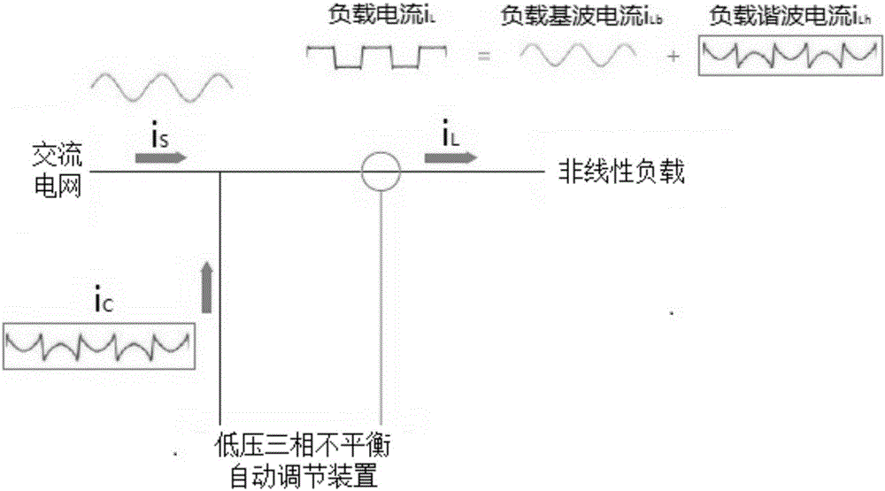
[0062] see figure 1 As shown, the low-voltage three-phase unbalance automatic adjustment device can filter out the ever-changing harmonics and reactive currents, not only has a thorough filtering effect, but also overcomes the shortcomings of the passive filter, which is bulky and easy to resonate with the system. .

[0063] Basic principles such as figure 1 Shown: The device is ...


PUM


Abstract

The invention discloses a low-voltage three-phase imbalance automatic regulating device. The automatic regulating device comprises a low-voltage distribution system, a detection unit, a reactive compensation controller, a switching unit and an active filter device, wherein the low-voltage distribution system is used for transferring a three-phase voltage signal and a three-phase current signal to the detection unit; the detection unit is used for transferring signals detected by a load to the active filter device, and the active filter device is used for processing three-phase imbalance harmonic signals in a power grid and compensating a harmonic current; the detection unit is used for transferring signals detected at a system side to the reactive compensation controller, and the reactive compensation controller is used for carrying out comparison operation and outputting the signals to the switching unit; and the switching unit is used for regulating the voltage and current of the low-voltage distribution system. The low-voltage three-phase imbalance automatic regulating device disclosed by the invention is specially designed for electric power departments and power consumers, the reactive power can be effectively compensated, harmonic waves can be treated, the quality of electric energy can be improved, and the loss can be reduced; and the low-voltage three-phase imbalance automatic regulating device is necessary energy-saving equipment.

Description

technical field [0001] The invention belongs to the field of electric power control, and relates to a low-voltage three-phase unbalance automatic adjustment device. Background technique [0002] With the development of industry, the problem of harmonic and reactive power compensation in the power system is becoming more and more serious, which distorts the voltage waveform of the power supply system, increases the power loss of the transmission line and the loss of electrical equipment, and also reduces the power supply system. Power quality, while harmonics can also cause accidents in the power system. Therefore, in recent years, power supply departments and users have attached great importance to it. In the management of load, the power supply department should strengthen the management and detection of harmonic source load. With the important measure of energy saving and emission reduction proposed in the plan, more attention has been paid to the issue of harmonic and r...

Claims


Application Information

Patent Timeline
IPC IPC(8): H02J3/26H02J3/18H02J3/01
CPCH02J3/01H02J3/1842H02J3/26Y02E40/30Y02E40/50Y02E40/40
Inventor 张高峰
Owner 江苏谷峰电力科技股份有限公司
Why Eureka
Try Eureka