
Wireless charging device

A wireless charging and transmitting device technology, applied in the direction of circuit devices, electrical components, etc., can solve the problems of lack of flexibility, lack of communication control means, power waste, etc.

Active Publication Date: 2017-05-31
SHENZHEN JOINTRONIC TECH CO LTD
View PDF4 Cites 10 Cited by
  • Summary
  • Abstract
  • Description
  • Claims
  • Application Information

AI Technical Summary

Problems solved by technology

However, these solutions generally can only perform wireless charging simply, and communication between the transmitting end and the receiving end cannot be carried out. Therefore, there is a lack of communication control means, resulting in a lack of flexibility in the wireless charging process, and may also cause waste of power.

Method used


Image

  • Wireless charging device
  • Wireless charging device
  • Wireless charging device

Examples


Embodiment Construction

[0024] The following will clearly and completely describe the technical solutions in the embodiments of the present invention with reference to the accompanying drawings in the embodiments of the present invention. Obviously, the described embodiments are only some of the embodiments of the present invention, not all of them. Based on the embodiments of the present invention, all other embodiments obtained by persons of ordinary skill in the art without creative efforts fall within the protection scope of the present invention.

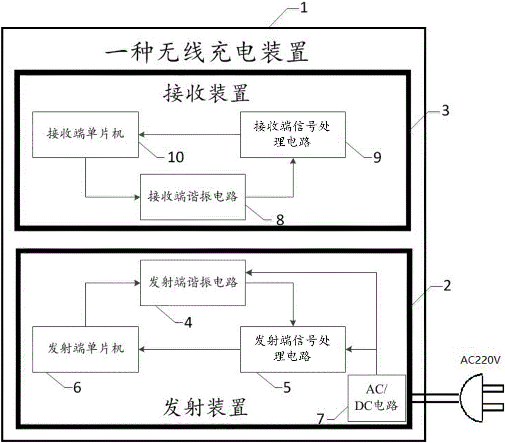
[0025] see figure 1 , which is a structural block diagram of a preferred embodiment of a wireless charging device provided by the present invention.

[0026] A wireless charging device 1 provided by an embodiment of the present invention includes a transmitting device 2 and a receiving device 3; the transmitting device 2 and the receiving device 3 of the wireless charging device 1 are respectively arranged in two upper and lower separable structural m...


PUM


Abstract

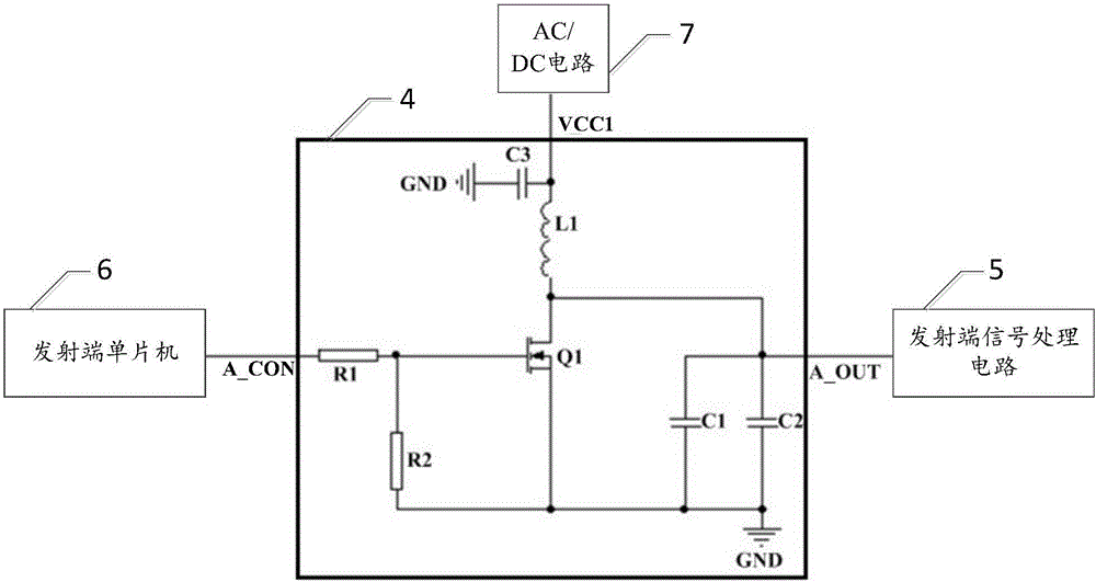
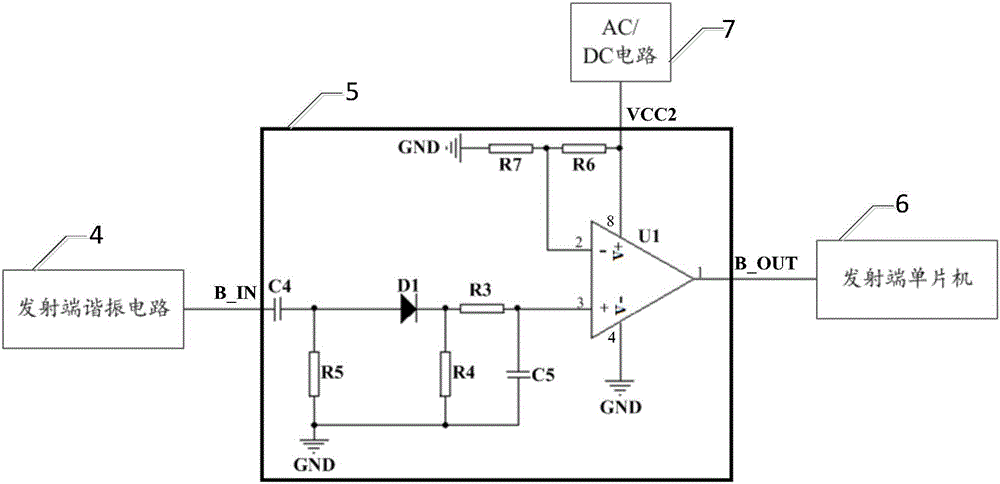
The invention discloses a wireless charging device. The wireless charging device is characterized in that a transmitting device comprises a transmitting end resonance circuit, a transmitting end signal processing circuit and a transmitting end single-chip microcomputer; the transmitting end resonance circuit is used for transmitting an instruction signal and receiving a response signal; the transmitting end processing circuit demodulates the received response signal to obtain an original response signal; the transmitting end single-chip microcomputer demodulates a PWM carrier signal output by the transmitting end single-chip microcomputer according to the original response signal; a receiving device comprises a receiving end resonance circuit, a receiving end signal processing circuit and a receiving end single-chip microcomputer; the receiving end resonance circuit is used for receiving the instruction signal and transmitting the response signal; the receiving end signal processing circuit demodulates the received instruction signal to obtain an original instruction signal; the receiving end single-chip microcomputer demodulates the PWM carrier signal output by the receiving end single-chip microcomputer according to the original response signal. By the wireless charging device, wireless charging can be achieved in a low-cost manner, and data communication between a transmitting end and a receiving end can be achieved during charging.

Description

technical field [0001] The present invention relates to the technical field of wireless charging, in particular to a wireless charging device. Background technique [0002] Wireless charging technology is a non-contact way, the transmitting end transmits electric energy to the adjacent receiving end, and a certain degree of process control can be realized by the communication between the transmitting end and the receiving end. At present, wireless charging technology has been used in mobile phones, electric toothbrushes, automobiles and other fields. Wireless charging technology can save the cost of wire materials in the wired mode, and the non-contact mode can also reduce the risk of strong electric breakdown and increase the safety of use. [0003] Wireless charging technology can be divided into two categories: one is the magnetic coupling mode, according to Lenz's law, after the magnetic flux between the coil and the coil changes, an induced voltage is generated on the ...

Claims


Application Information

Patent Timeline
Patent Type & Authority Applications(China)
IPC IPC(8): H02J50/80H02J50/12
Inventor 王刚
Owner SHENZHEN JOINTRONIC TECH CO LTD
Learn More