

Bearingless permanent magnet slice motor
A bearingless, thin-film technology, applied in synchronous motors with stationary armatures and rotating magnets, magnetic circuits, electric components, etc., can solve problems such as increasing production costs, increasing axial length, increasing motor volume, etc. The effect of copper loss, reduction of axial length, and improvement of working performance
- Summary
- Abstract
- Description
- Claims
- Application Information
AI Technical Summary
Problems solved by technology
Method used
Image

Examples
Embodiment Construction
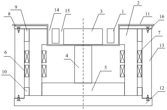
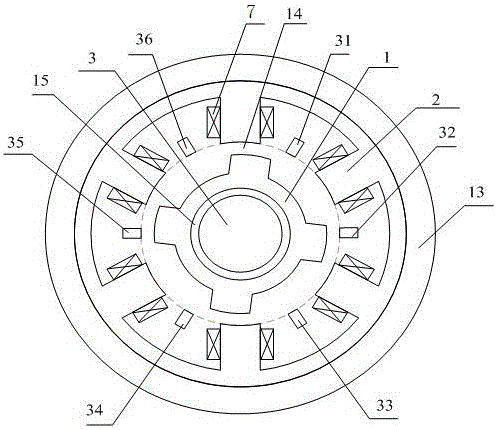
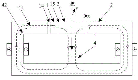
[0020] Such as figure 1 and figure 2 As shown, the present invention has a sheet rotor 1 and a stator 2 , the inner diameter of the stator 2 is larger than the outer diameter of the sheet rotor 1 , and the sheet rotor 1 is coaxially sleeved in the stator 2 . A cylindrical magnetic flux collection device 3 is coaxially sleeved inside the sheet rotor 1, and the magnetic flux collection device 3 is made of a magnetically conductive material. The inner diameter of the thin-film rotor 1 is larger than the outer diameter of the magnetic flux collecting device 3 , and a radial air gap 15 is left between the magnetic flux collecting device 3 and the thin-film rotor 1 . The central axis of the magnetic flux collecting device 3 is the central axis of the motor.
[0021] The sheet rotor 1 adopts a 4-pole salient pole structure. The stator 2 is composed of 6 identical L-shaped stator core columns, and the 6 identical L-shaped stator core columns are evenly distributed along the circum...
PUM
 Abstract
Description
Claims
Application Information