Composite excitation amorphous alloy axial flux motor

A technology of axial magnetic flux and electric excitation, applied in the direction of magnetic circuits, electromechanical devices, electrical components, etc., can solve problems such as high energy consumption, small output torque, and complex structure

Active Publication Date: 2020-10-30
SHENYANG POLYTECHNIC UNIV
View PDF10 Cites 0 Cited by
  • Summary
  • Abstract
  • Description
  • Claims
  • Application Information

AI Technical Summary

Problems solved by technology

[0003] In order to pursue the high power torque density, high efficiency and controllable effect of the magnetic field of the motor, many researchers have proposed different types of topological structures in the form of mixed excitation to solve the problem that the magnetic field of the traditional permanent magnet synchronous motor is difficult to adjust and is not conducive to the weakening of the magnetic field. and other issues, but there are still defects in varying degrees:
However, its permanent magnet is located in the stator, and the assembled stator core increases the difficulty of process and assembly, and the electric excitation magnetic circuit passes through the permanent magnet, which increases the copper loss of the excitation winding.
[0005] (2) Chinese patent CN201310203116 .0 proposes a magnetic levitation bearing disc type hybrid excitation double salient pole wind power generator, aiming at the existing problems of the existing magnetic levitation wind power generator system, such as too complicated structure, high energy consumption, and not being suitable for small and medium wind turbines, etc.
[0006] (3) Chinese patent CN201610317337.4 proposes a hybrid excitation axial flux modulation composite structure motor, the purpose is to solve the problem of low output torque of the existing hybrid excitation motor
However, the stator teeth are affected by the magnetic flux generated by the armature winding, electric excitation winding and permanent magnet at the same time, and it is easy to reach a saturation state, which reduces the magnetic adjustment ability of the motor.

Method used


Image

  • Composite excitation amorphous alloy axial flux motor
  • Composite excitation amorphous alloy axial flux motor

Examples


Embodiment Construction

[0033] Below in conjunction with accompanying drawing, the present invention will be further described:

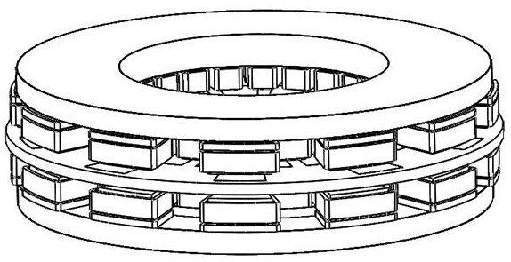
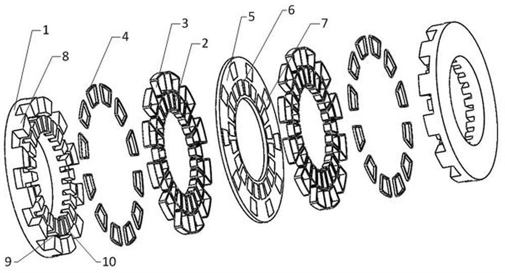
[0034] The invention provides a composite excitation amorphous alloy axial flux motor, such as figure 1 , figure 2 As shown, it includes combined amorphous alloy stator core, permanent magnet area armature winding, electric excitation area armature winding, electric excitation winding, rotor bracket, permanent magnet and ferromagnetic pole; it is characterized in that: the combined stator core is radially Divided into three parts, from the inside to the outside are the stator in the permanent magnet area, the magnetic isolation area, and the stator in the electric excitation area; Iron core and axial correspondence; the stator core in the electric excitation area has 6*n open slots, n is a positive integer, and there are 5*n ferromagnetic poles in the rotor corresponding to the axial direction; the permanent magnet area There are 10*n permanent magnets in the rotor;

[0...


PUM


Abstract

A hybrid magnetic field controllable axial flux motor comprises two amorphous alloy stators and a rotor arrange between that two stators; The stator core of stator is divided into three parts along the radial direction, which are stator core in permanent magnet region, stator core in magnetic isolation region and stator core in electric excitation region. The armature winding of the permanent magnet region is arranged on the stator core of the permanent magnet region; The armature winding of the electric excitation region is arranged on the stator core of the electric excitation region; A permanent magnet and a ferromagnetic pole are embedded on the rotor bracket of the rotor part, respectively corresponding to the stator iron core of the electric excitation region and the stator iron coreof the permanent magnet region in the axial direction. The utility model has the advantages of simple manufacture, low loss, high power density and wide range of weak magnetic field expansion speed.

Description

technical field [0001] The invention belongs to the field of axial flux motors, and mainly relates to a composite excitation amorphous alloy axial flux motor. Background technique [0002] As a new type of soft magnetic material, amorphous alloy strip has excellent magnetic properties, corrosion resistance, wear resistance, high strength, high hardness and high resistivity, and its thickness is only 0.025mm. Compared with the traditional silicon steel sheet, the amorphous alloy has very small core loss especially in the high frequency range, so the amorphous alloy strip is very suitable for high-speed high-frequency motors. The traditional amorphous alloy axial flux permanent magnet synchronous motor adopts the permanent magnet structure of double rotor and single stator. The surface of the motor rotor with this structure is covered with permanent magnets, and the stator is covered with armature windings on both sides, which has high power density. , high torque density and...

Claims


Application Information

Patent Timeline
Patent Type & Authority Patents(China)
IPC IPC(8): H02K16/04H02K1/27H02K1/12H02K15/02
CPCH02K1/12H02K1/2793H02K15/02H02K16/04H02K2201/12
Inventor 佟文明吴胜男王帅荆明
Owner SHENYANG POLYTECHNIC UNIV
Why Eureka
Try Eureka