Rotor of alternating current permanent magnet servo motor

A technology for permanent magnet servo motors and rotors, which is applied in the direction of magnetic circuit rotating parts, magnetic circuits, electrical components, etc., and can solve problems such as large magnetic flux leakage coefficients

Inactive Publication Date: 2017-05-31
FOSHAN INST OF INTELLIGENT EQUIP TECH +3
View PDF4 Cites 3 Cited by
  • Summary
  • Abstract
  • Description
  • Claims
  • Application Information

AI Technical Summary

Problems solved by technology

However, the magnetic flux leakage coefficient of this rotor structure is relatively large, refer to figure 2 , using the finite element method to analyze the existing rotor, the existing rotor has a magnetic bridge leakage magnetic circuit H1 on the side close to the rotating shaft

Method used


Image

  • Rotor of alternating current permanent magnet servo motor
  • Rotor of alternating current permanent magnet servo motor
  • Rotor of alternating current permanent magnet servo motor

Examples


Embodiment 1

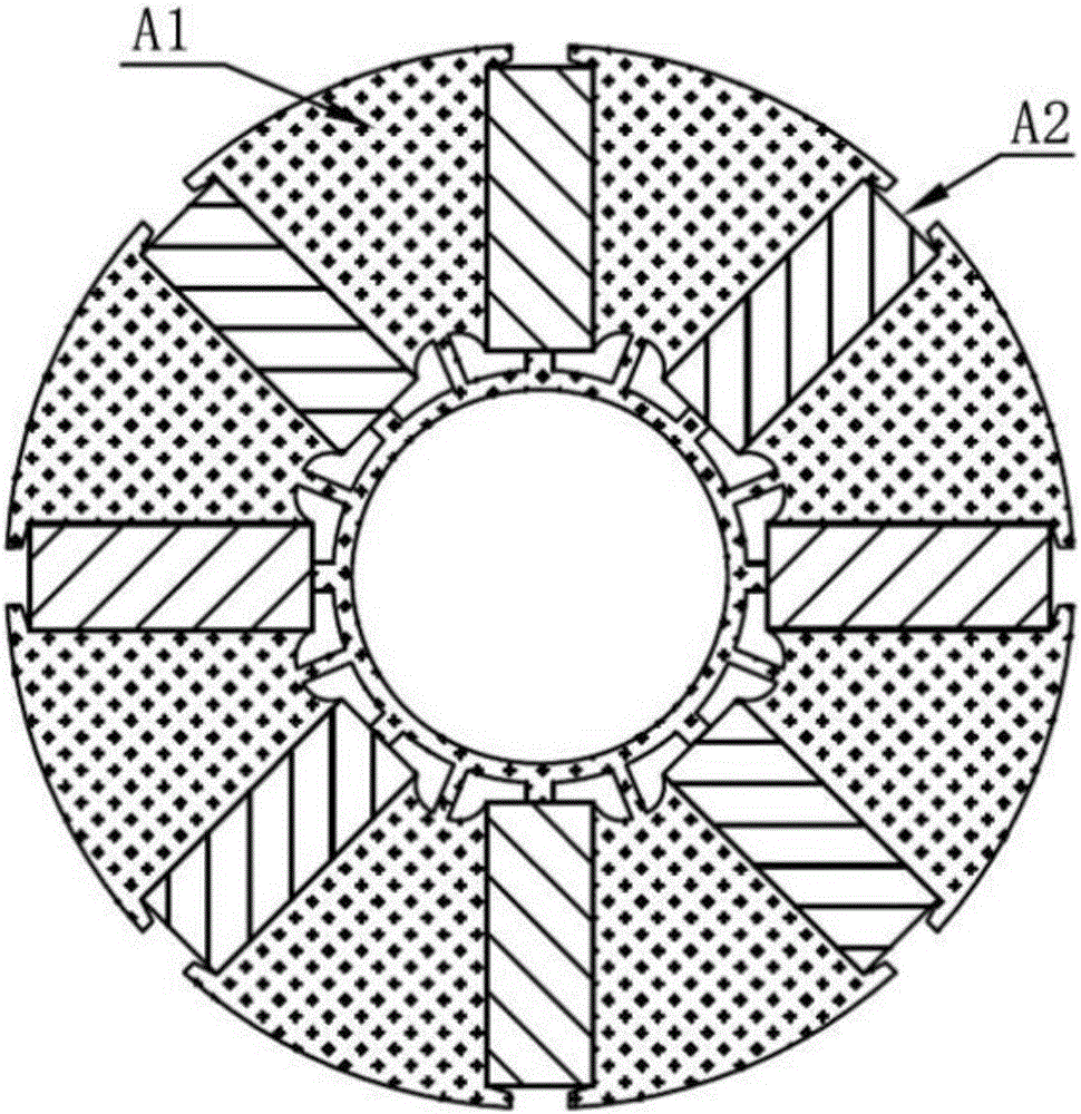
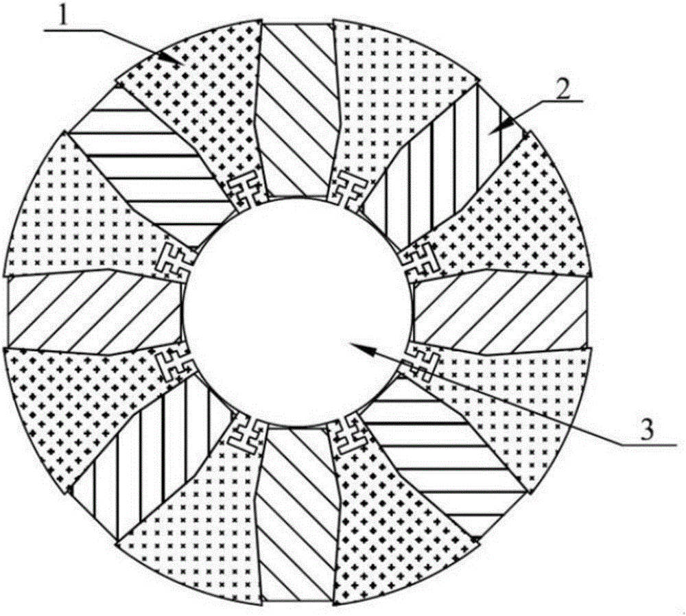
[0021] refer to image 3 and Figure 4 , a rotor of an AC permanent magnet servo motor, including a rotating shaft 3, a plurality of permanent magnets 2 and a plurality of independent iron cores 1, and the independent iron cores 1 are pressed by multiple identical laminations to form a composite core, wherein the laminations It is fan-shaped, and a second-order guide groove 11 is provided at a position close to the rotating shaft 3. The side of the lamination includes two edges 12a, 12b that form an angle with each other. Using a plurality of identical laminations to press the independent iron core 1 is beneficial to reduce the cost of production equipment, and the cost of producing sheet-shaped components is lower than that of producing block-shaped components, which is beneficial to popularization and application of the rotor with this structure.

[0022] The independent iron core 1 is arrayed around the rotating shaft 3. The rotating shaft 3 is a cylinder, and the surface ...


PUM


Abstract

The invention discloses a rotor of an alternating current permanent magnet servo motor. The rotor comprises a rotating shaft, a plurality of permanent magnets and a plurality of independent iron cores, wherein at least two identical planes are arranged between the iron cores; the iron cores surround the rotating shaft; the rotating shaft is connected with the iron cores; a cavity is formed between two adjacent iron cores; the permanent magnets are embedded in the cavities; and the rotating shaft is a component made of a non-magnetic material. The independent iron cores surround the rotating shaft, the rotating shaft is made of the non-magnetic material in a casting manner, so that magnetic flux leakage does not exist in space among the connected independent iron cores; all magnetic lines of force move towards a stator side; and a leakage path of a magnetic bridge can be avoided.

Description

technical field [0001] The invention relates to the technical field of motor equipment, in particular to a rotor of an AC permanent magnet servo motor. Background technique [0002] The motor with tangential magnetization structure of permanent magnet has the effect of "magnetism concentration", so this structure is widely used in the rotor of servo motor. [0003] refer to figure 1 , the current rotor usually has a rotating shaft and an iron core A1, wherein the center of the iron core has a central hole parallel to the rotating shaft. The slots accommodate permanent magnets. [0004] The magnetic flux under one pole pitch of this structure is provided by two adjacent permanent magnets connected in parallel, which can obtain a larger magnetic flux per pole, and the advantages of motors with more poles, such as the fractional slot concentrated winding structure, are more prominent. However, the magnetic flux leakage coefficient of this rotor structure is relatively large,...

Claims


Application Information

Patent Timeline
Patent Type & Authority Applications(China)
IPC IPC(8): H02K1/27
CPCH02K1/274H02K1/276
Inventor 李大伟陈红董明海文益雪向红斌王现立郑卓梁焕辉
Owner FOSHAN INST OF INTELLIGENT EQUIP TECH
Why Eureka
Try Eureka