A permanent solenoid magnet

A solenoid and magnet technology, applied in the direction of permanent magnets, etc., can solve the problems of reducing the effective magnetic field space magnetic field strength and magnetic field uniformity, electromagnetic equipment interference, large magnetic flux leakage, etc., achieving light weight, improving utilization, and reducing magnetic leakage. Effect

Inactive Publication Date: 2017-09-29
INST OF ELECTRICAL ENG CHINESE ACAD OF SCI
View PDF2 Cites 0 Cited by
  • Summary
  • Abstract
  • Description
  • Claims
  • Application Information

AI Technical Summary

Problems solved by technology

However, there is still magnetic flux leakage in the non-effective magnetic field space of the above-mentioned magnetic circuit structure, especially at both ends of the axial direction. This not only reduces the magnetic field strength and uniformity of the effective magnetic field space, but also affects the Electromagnetic equipment that interferes and affects

Method used


Image

  • A permanent solenoid magnet
  • A permanent solenoid magnet
  • A permanent solenoid magnet

Examples


Embodiment Construction

[0012] The present invention will be further described below in conjunction with the accompanying drawings and specific embodiments.

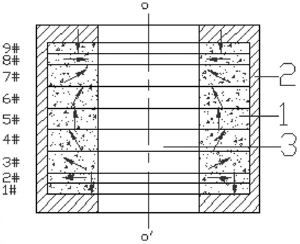
[0013] figure 1 It is a specific embodiment of the present invention.

[0014] Such as figure 1 As shown, the present invention is composed of 9 magnetic rings 1, that is, 2n+3=9 magnetic rings 1 and a magnetically permeable casing 2, n=3; 9 magnetic rings are stacked sequentially along the axis oo', and the casing 2 is placed coaxially The outer circumference of the nine magnetic rings form a hollow cylinder. The inner space 3 of the cylinder is a magnetic field space. The geometric structure and magnetization direction of the 9 magnetic rings 1 are axisymmetric; the 2# magnetic ring to the 8# magnetic ring form the main magnetic circuit, and the magnetization direction changes counterclockwise from the 2# magnetic ring to the 8# magnetic ring . Viewed from any axial section, the magnetization directions of adjacent magnetic rings in the ...


PUM

PropertyMeasurementUnit
lengthaaaaaaaaaa

Abstract

A permanent solenoid solenoid magnet has axial symmetry in geometric structure, and consists of 2n+3 magnetic rings (1), n>2, a magnetically permeable shell (2) and a cylindrical magnetic field space (3). A magnetic field with axial symmetry is generated in the cylindrical space, and an axial magnetic field is mainly generated in the axial middle region of the magnetic field space (3). 2n+3 magnetic rings (1) are stacked in sequence along the axial direction, the inner cylindrical space of 2n+3 magnetic rings (1) is the magnetic field space (3), and the shell (2) is coaxially placed on 2n+3 magnetic rings ( 1) Perimeter. The main magnetic circuit of the present invention is composed of 2n+1 magnetic rings (1) in the middle, and the magnetic field intensity of the magnetic field space (3) is greatly improved by utilizing the axial magnetic field after the magnetic ring is decomposed and the radial magnetic field to superimpose each other; the main magnetic circuit The two ends adopt the end magnetic ring with the magnetic moment opposite to that of the n+2th magnetic ring, and at the same time, a magnetically permeable shell (2) is installed on the outer periphery of the 2n+3 magnetic rings (1), thereby reducing the magnetic flux leakage on the outer periphery of the magnet.

Description

technical field [0001] The invention relates to a permanent magnet. Background technique [0002] Plasma is widely used in the fields of space, materials, microelectronics, environment and energy. Helicon wave discharge plasma is a kind of high-density plasma with high ionization rate. broad attention. A helicon wave is a wave with a whistling wave mode propagating in a finite-diameter, axially magnetized cylindrical plasma. A helicon wave plasma device usually uses one or more electromagnetic coils to provide an axially applied magnetic field. Electromagnetic coils not only require a huge DC power supply, but also have a large Joule heat loss, requiring peripheral cooling facilities. This makes the cost of the electromagnetic coil high, the energy consumption is large, and the volume (weight) is large, and it is not suitable for occasions with strict requirements on the external dimension, weight and maneuverability. With the improvement of the performance of permanent ...

Claims


Application Information

Patent Timeline
Patent Type & Authority Patents(China)
IPC IPC(8): H01F7/02
Inventor 赵凌志彭爱武刘保林王锋李然李建夏琦董增仁沙次文
Owner INST OF ELECTRICAL ENG CHINESE ACAD OF SCI
Why Eureka
Try Eureka