An Optimal Method for Dealing with Multiple Array Antenna Signal Errors

A technology of signal error and optimization method, which is applied in the direction of transmission monitoring, electrical components, transmitter monitoring, etc., and can solve the problems that large-scale antenna arrays are not applicable, and various array errors are not considered.

Active Publication Date: 2020-05-12
UNIV OF ELECTRONICS SCI & TECH OF CHINA
View PDF4 Cites 0 Cited by
  • Summary
  • Abstract
  • Description
  • Claims
  • Application Information

AI Technical Summary

Problems solved by technology

However, most of the existing comprehensive methods do not take into account the existence of multiple array errors, or are not suitable for large antenna arrays

Method used


Image

  • An Optimal Method for Dealing with Multiple Array Antenna Signal Errors
  • An Optimal Method for Dealing with Multiple Array Antenna Signal Errors
  • An Optimal Method for Dealing with Multiple Array Antenna Signal Errors

Examples


Embodiment Construction

[0048] The number of elements of the linear array considered in this embodiment is N=20, the distance between the elements d=λ / 2 (λ is the wavelength of the incoming wave), and then the center frequency fc is set to 9.57e9 Hz.

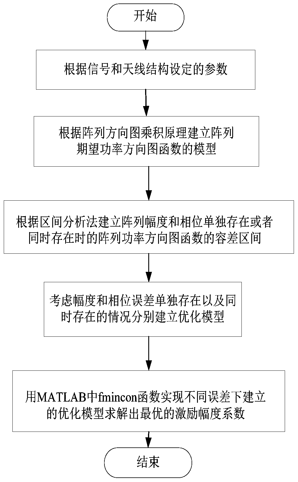
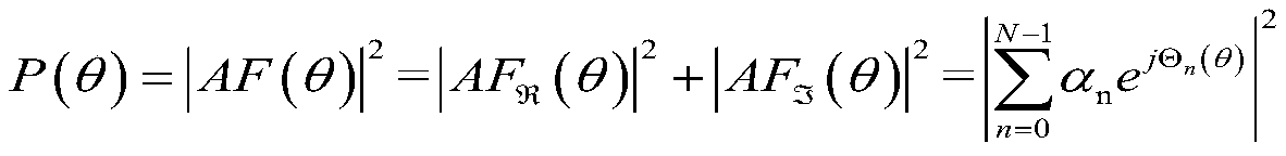
[0049] Step 1: According to the received signal and the structure of the antenna itself, set the corresponding parameters, and thus obtain the model of the array factor AF(θ).

[0050] Step 1.1: Assuming that there is no mutual coupling between the array elements, the excitation amplitude is a n , with Is the actual amplitude and the expected amplitude a n The maximum deviation between (n=0,1,...,N-1), considering the maximum deviation of the excitation amplitude of the array is (I.e. the percentage error is ).

[0051] with Are the minimum and maximum values ​​of the n-th amplitude coefficient, and the tolerance interval can be expressed as

[0052] Step 1.2: The phase of the array factor is Is the excitation phase, n=0,1,...,N-1, N is the number of a...


PUM


Abstract

The invention discloses an optimization method for processing various array antenna signal errors, which relates to the field of antenna array signal processing, specifically, an optimal design method for dealing with the existence of various array errors. According to the measured array receiving signal amplitude error and array element phase error, the IA algorithm is used to determine the array factor model, and the precise power pattern change boundary is calculated, and the convex optimization model of the array excitation amplitude is established, and according to the obtained optimization The incentive weights are synthesized to produce a power pattern that meets the performance requirements. Compared with the IA‑PSO algorithm using the global random search method, this method not only can obtain better array excitation parameters under the same error conditions, but also has better robustness to the array amplitude and phase errors. Important parameters such as side lobe level, main lobe width and array direction coefficient can be effectively controlled in antenna design.

Description

Technical field [0001] The present invention relates to the field of antenna array signal processing, in particular, it is an optimized design method for processing multiple array errors. Background technique [0002] With the continuous development of information technology, array antennas have become a hot spot in antenna neighborhood research and application in recent years. They are widely used in military and social life, such as radar monitoring, satellite communications, and so on. However, in these applications, the array antenna needs to analyze and reduce the mismatch between the ideal numerical integrated radiation pattern and the actual measurement result through a time-consuming and expensive radiation characteristic measurement process. In order to ensure that the antenna achieves the expected radiation characteristics, it is necessary to correct the control parameters of the antenna, such as the number of elements, the spacing of the elements, and the excitation we...

Claims


Application Information

Patent Timeline
Patent Type & Authority Patents(China)
IPC IPC(8): H04B17/12H04B17/391
CPCH04B17/12H04B17/391
Inventor 张瑛赵丹旎汪婷静王琼龙政斌
Owner UNIV OF ELECTRONICS SCI & TECH OF CHINA
Why Eureka
Try Eureka