A jammer and its control method

A control method and jammer technology, which is applied in the field of information jamming, can solve the problems of not being able to meet the high requirements of isolation of small platform jammers, insufficient optimization, and poor jamming effect, so as to improve the effect of reconnaissance and jamming, and the circuit structure is simple Optimized effect

Active Publication Date: 2019-06-21
上海工业控制安全创新科技有限公司
View PDF5 Cites 0 Cited by
  • Summary
  • Abstract
  • Description
  • Claims
  • Application Information

AI Technical Summary

Problems solved by technology

[0005] However, traditional methods still cannot meet the high isolation requirements of small-platform jammers. Therefore, it is necessary to find a method to effectively weaken the impact of jamming signals on the reconnaissance and receiving system. Increasing the isolation of jammers from transceivers is an important issue that urgently needs to be solved in forwarding jamming technology. question
At the same time, the traditional jammer has a complex circuit structure, is not optimized enough, and the jamming effect is not good

Method used


Image

  • A jammer and its control method
  • A jammer and its control method

Examples


Embodiment 1

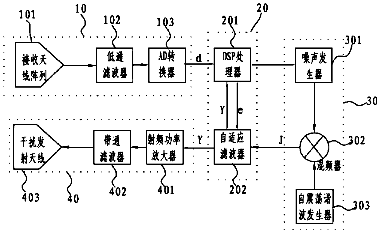
[0032] refer to figure 1 , a jammer, comprising a receiving circuit 10, a signal processing circuit 20, an interference signal generating circuit 30 and a transmitting circuit 40, the signal output end of the receiving circuit 10 is connected to the first signal input end of the signal processing circuit 20, and the signal processing The first signal output end of circuit 20 is connected with the signal input end of interference signal generation circuit 30, the signal output end of interference signal generation circuit 30 is connected with the second signal input end of signal processing circuit 20, the second signal of signal processing circuit 20 The output end is connected with the signal input end of the transmitting circuit 40 .

[0033]In another embodiment, the signal processing circuit 20 includes a DSP processor 201 and an adaptive filter 202 connected in communication; the first signal input end of the DSP processor 201 is connected to the signal output end of the ...


PUM


Abstract

The invention discloses an interference unit, comprising a receiving circuit, a signal processing circuit, an interference signal generation circuit and a transmitting circuit. A signal output end of the receiving circuit is connected with a first signal input end of the signal processing circuit. A first signal output end of the signal processing circuit is connected with a signal input end of the interference signal generation circuit. The signal output end of the interference signal generation circuit is connected with a second signal input end of the signal processing unit. A second signal output end of the signal processing circuit is connected with the signal input end of the transmitting circuit. The invention also discloses a control method for the interference unit. According to the interference unit and the method, the interference signals entering a receiving antenna array can be effectively eliminated; useful sensing signals are obtained; and the interference signals with communication frequency the same to that of an interference target is generated, thereby forming strong interference to the interference target, so the interference target cannot work normally and is thoroughly out of control. The circuit structure is relatively simple and optimized.

Description

technical field [0001] The invention belongs to the technical field of information interference, and in particular relates to a jammer and a control method thereof. Background technique [0002] With the continuous development of electronic information technology, jammers, as an active interference source, are increasingly used in technical fields such as information security. For example, in the process of information transmission, the interference signal sent by the jammer is coupled to the transmitted In the signal, it is difficult for non-receivers to steal the real transmission signal to achieve the purpose of information transmission security; another example is that jammers are used in radar, drone and anti-drone fields to achieve the purpose of reconnaissance and interference. [0003] If jamming and reconnaissance work at the same time, there is a problem of isolation between the reconnaissance receiving antenna and the jamming transmitting antenna. During the jamm...

Claims


Application Information

Patent Timeline
Patent Type & Authority Patents(China)
IPC IPC(8): H04K3/00
CPCH04K3/42H04K3/825
Inventor 张祖锋
Owner 上海工业控制安全创新科技有限公司
Why Eureka
Try Eureka