Free electron laser radiation source for the EUV

A radiation source and laser technology, applied in the field of FEL radiation source, can solve problems such as operational distortion

Active Publication Date: 2017-05-31
ASML NETHERLANDS BV
View PDF4 Cites 5 Cited by
  • Summary
  • Abstract
  • Description
  • Claims
  • Application Information

AI Technical Summary

Problems solved by technology

[0008] The use of clearing gaps between electron beams can distort the operation of the energy recovery LINAC

Method used


Image

  • Free electron laser radiation source for the EUV
  • Free electron laser radiation source for the EUV
  • Free electron laser radiation source for the EUV

Examples


Embodiment Construction

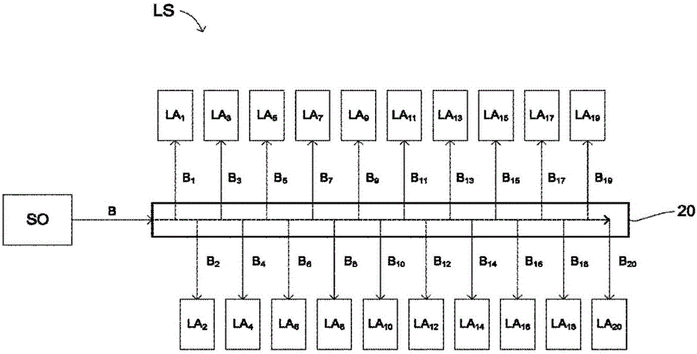
[0112] figure 1 A lithographic system LS is shown, comprising: a radiation source SO, a beam splitting device 20 and a plurality of lithographic devices LA 1 -LA 20 . The radiation source SO comprises at least one free electron laser and is configured to generate an extreme ultraviolet (EUV) radiation beam B (which may be referred to as a main beam). The main radiation beam B is split into multiple radiation beams B 1 -B 20 (which may be referred to as branched beams), the radiation beam B 1 -B 20 Each of them is guided to the lithographic apparatus LA by the beam splitting apparatus 20 1 -LA 20 Different lithography equipment in. Branch Radiation Beam B 1 -B 20It may be successively branched from the main radiation beam B, wherein each branch radiation beam is branched off from the main radiation beam B downstream of a previous branch radiation beam. The beam splitting device may for example comprise a series of mirrors (not shown), each of which mirrors is configu...


PUM


Abstract

Passage through LINACs of electron bunches in their acceleration phase is co-ordinated with passage through the LINACs of electron bunches in their deceleration phase. Each successive pair of electron bunches are spaced in time by a respective bunch spacing, in accordance with a repeating electron bunch sequence. The electron source provides clearing gaps in the electron bunch sequence to allow clearing of ions at the undulator. The electron source provides the clearing gaps in accordance with a clearing gap sequence such that, for each of the plurality of energy recovery LINACS, and for substantially all of the clearing gaps:- for each passage of the clearing gap through the LINAC in an acceleration phase or deceleration phase the clearing gap is co-ordinated with a further one of the clearing gaps passing through the LINAC in a deceleration phase or acceleration phase thereby to maintain energy recovery operation of the LINAC.

Description

[0001] Cross References to Related Applications [0002] This application claims the benefit of European application 14181152.1 filed on 15.08.2014 and European application 15170640.5 filed on 04.06.2015 and which are hereby incorporated by reference in their entirety. technical field [0003] The present invention relates to a free electron laser (FEL) radiation source, eg a FEL radiation source configured to generate radiation having a wavelength in the range of 4nm to 25nm. The radiation source may eg be configured to provide radiation to the lithographic apparatus for projecting the pattern from the patterning device onto the substrate. Background technique [0004] It is known to use a free electron laser (FEL) radiation source to generate radiation at a desired wavelength, wherein an electron beam comprising a periodic sequence of electron bunches is passed through an undulator to generate radiation. These sources can be used to generate radiation in the range of 4nm ...

Claims


Application Information

Patent Timeline
Patent Type & Authority Applications(China)
IPC IPC(8): H01S3/09H01S3/00
CPCH01S3/0071H01S3/0903H01S3/0959H01S3/1024H01S3/1103
Inventor 安德雷·亚历山德罗维奇·尼基佩洛夫T·J·克嫩J·J·M·范海尔福尔特W·J·恩格伦G·J·H·布鲁斯阿德G·G·波尔特E·R·鲁普斯特拉
Owner ASML NETHERLANDS BV
Why Eureka
Try Eureka