
Fitness trainer

A training device and crankshaft technology, applied in the field of fitness training devices, can solve the problems of prone to accidents, complex equipment structure, loud noise, etc., and achieve the effects of increasing rotational resistance, convenient training and operation, and reducing noise.

Inactive Publication Date: 2017-06-06
杭州杭韵电器有限公司
View PDF6 Cites 1 Cited by
  • Summary
  • Abstract
  • Description
  • Claims
  • Application Information

AI Technical Summary

Problems solved by technology

At present, there are not many training equipment for upper limbs on the market, and most of them are purely mobile equipment, which cannot adjust the training strength according to the needs of trainers. The most common ones are the turntables used for hand training for the elderly in parks or communities.
However, some other upper limb training equipment with strength conditions have the following defects: 1. Due to the complex structure of the equipment and many accessories, the whole is bulky; 2. The noise is large due to the friction between the accessories during use; Accidents occur, causing users to be injured; 4. High requirements for the site and high equipment costs

Method used


Image

  • Fitness trainer
  • Fitness trainer
  • Fitness trainer

Examples


Embodiment 1

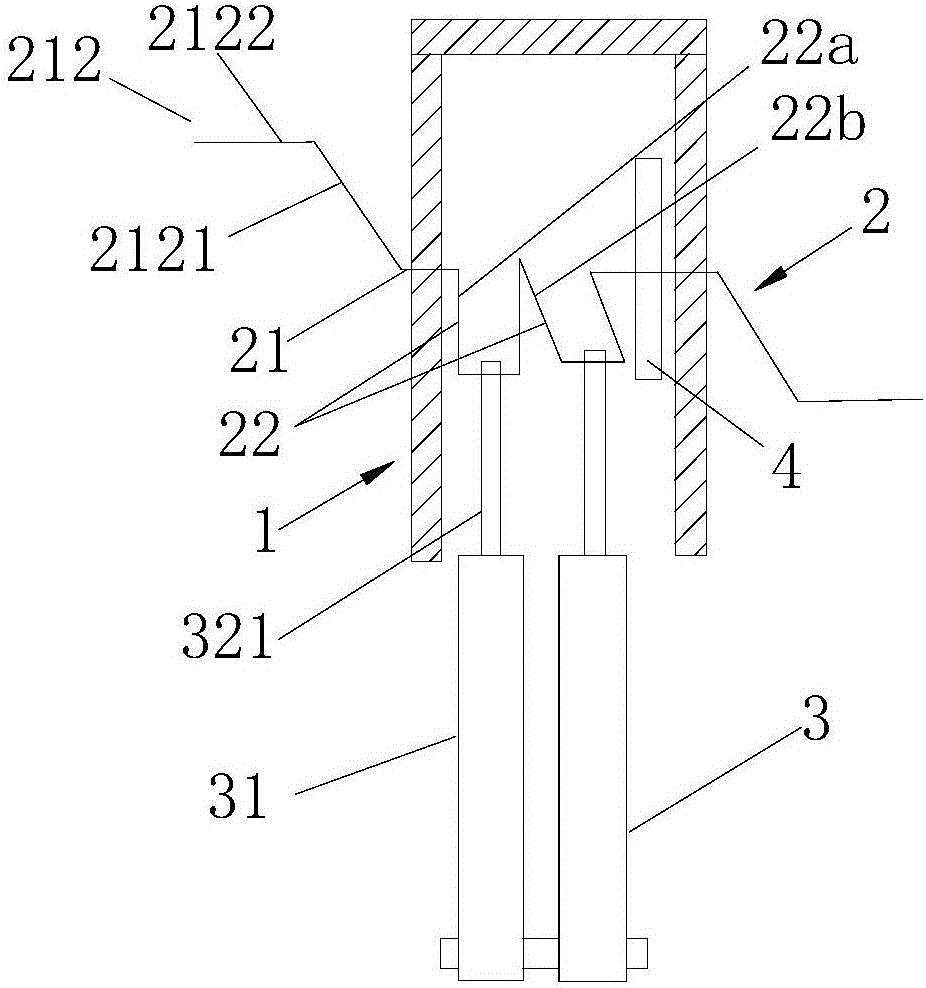
[0031] Embodiment one: if figure 1 , 3, Shown in 4, the present embodiment comprises frame 1, and the crankshaft 2 that horizontal arrangement is installed on this frame 1, and this crankshaft 2 and frame 1 are rotationally matched. The crankshaft 2 adopts a traditional crankshaft structure. The crankshaft 2 includes a main journal 21, a connecting rod journal 23, and a crank 22 for connecting the main journal 21 and the connecting rod journal 23. The axial direction of the main journal 21 is parallel to the axial direction of the connecting rod journal 23. The crank 22 is arranged perpendicular to the main journals 21 , and the crank 22 includes a first crank 22 a fixedly connected to one of the pin journals 23 , and a second crank 22 b fixedly connected to the other pin journal 23 . Among them, the number of connecting rod journals 23 is two; a flywheel 4 is fixed on the main journal 21, and the plane where the flywheel 4 is located is vertically arranged with the main jour...

Embodiment 2

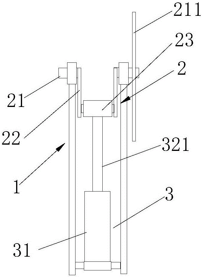
[0036] Embodiment two: if figure 2 As shown, the difference from Embodiment 1 is only that a turntable 211 is coaxially fixed at the main journal 21 , and the plane where the turntable 211 is located is perpendicular to the axial direction of the main journal 21 .

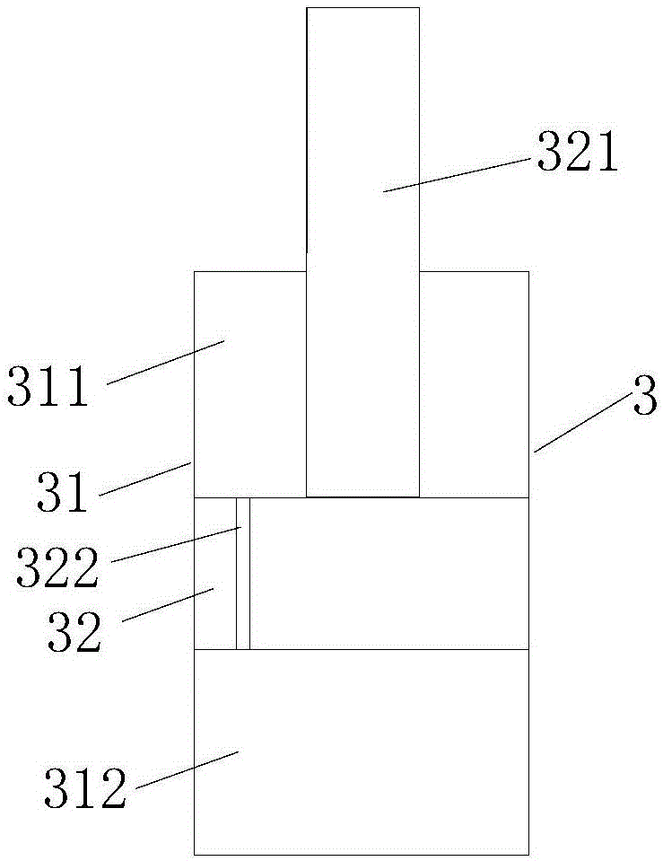
[0037] In the present invention, the rotation of the crankshaft 2 is realized by turning the turntable 211, thereby driving the connecting rod neck 23 on the crankshaft 2 to rotate together. Since the end of the piston rod 321 is hinged with the connecting rod neck 23, the function of the crankshaft 2 here is to The torque is converted into reciprocating motion of the piston rod 321 in the piston hydraulic cylinder 3 . Because the piston rod 321 needs power input when overcoming the hydraulic oil to do work, it is necessary to use body parts to rotate the turntable 211 through different fitness methods, so that the turntable 211 drives the crank 22 to rotate, so as to achieve the purpose of fitness. The turntable...


PUM


Abstract

The invention discloses a fitness trainer. The fitness trainer comprises a machine frame, a crankshaft, rocking handles and a damping device; the crankshaft is rotatably mounted at the machine frame and comprises a main shaft neck, a connecting rod neck, and a crank which is used for connecting the main shaft neck and the connecting rod neck; the rocking handles are fixed to the two end parts in the axial direction of the crankshaft; the damping device is fixed at the machine frame, is used for providing rotating resistance for the crankshaft, and is a piston type hydraulic cylinder; the axial direction of the piston type hydraulic cylinder is perpendicular to the axial direction of the crankshaft; a cylinder body is in hinged cooperation with the machine frame; the end part of a piston rod which is positioned out of the cylinder body is in hinged cooperation with the connecting rod neck. The overall trainer can achieve the purpose of keeping fit by only five parts, so that the structure is simple, and a training operation is convenient; the exercising force can be controlled by increasing the rotating resistance of the crankshaft; the damping device adopts a hydraulic cylinder mode, and the friction among parts is reduced, so that noises and the service life loss of the fitness trainer when the fitness trainer is operated are greatly reduced; bi-directional rotation, namely, clockwise movement and anticlockwise movement, can be realized by the rocking handles, and directional limitation is avoided.

Description

technical field [0001] The invention relates to a fitness training device, especially a fitness training device. Background technique [0002] In modern society, with the extension of working hours, the acceleration of the pace of life, and the increase of work pressure, people's physical condition is getting worse and worse, and there are more and more sub-healthy people. Therefore, office fitness equipment, martial arts fitness equipment, Tai Chi The market of fitness equipment is expanding rapidly, but the existing fitness equipment products are too lagging behind to meet and adapt to the potential needs of the society. [0003] With the improvement of scientific awareness, fitness pays more attention to scientific training, which is mainly reflected in the science of training methods and the science of training equipment. At present, there are not many training equipment for upper limbs on the market, and most of them are purely mobile equipment, which cannot adjust the...

Claims


Application Information

Patent Timeline
Patent Type & Authority Applications(China)
IPC IPC(8): A63B21/008A63B71/06
CPCA63B21/0083A63B71/0619A63B2220/17
Inventor 杨红春林辉杰陈剑
Owner 杭州杭韵电器有限公司
Learn More