Low power consumption circuit and its control method

A low power consumption, circuit technology, applied in the field of portable systems, can solve the problem of high dynamic power consumption of the chip, and achieve the effect of reducing dynamic power consumption, reducing dynamic power consumption, and simple logic structure

Active Publication Date: 2019-08-16
GREE ELECTRIC APPLIANCES INC
View PDF5 Cites 0 Cited by
  • Summary
  • Abstract
  • Description
  • Claims
  • Application Information

AI Technical Summary

Problems solved by technology

[0005] The embodiment of the present invention provides a low power consumption circuit and its control method, so as to at least solve the technical problem of high dynamic power consumption inside the chip in the portable system in the prior art

Method used


Image

  • Low power consumption circuit and its control method
  • Low power consumption circuit and its control method
  • Low power consumption circuit and its control method

Examples


Embodiment 1

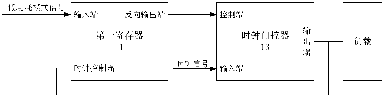
[0026] According to an embodiment of the present invention, an embodiment of a low power consumption circuit is provided, figure 1 is a schematic diagram of a low power consumption circuit according to an embodiment of the present invention, such as figure 1 As shown, the low-power circuit includes:

[0027] The first register 11, the input terminal of the first register inputs the low power mode signal, and is used for outputting the low level signal at the reverse output terminal of the first register when the low power mode signal is a high level signal.

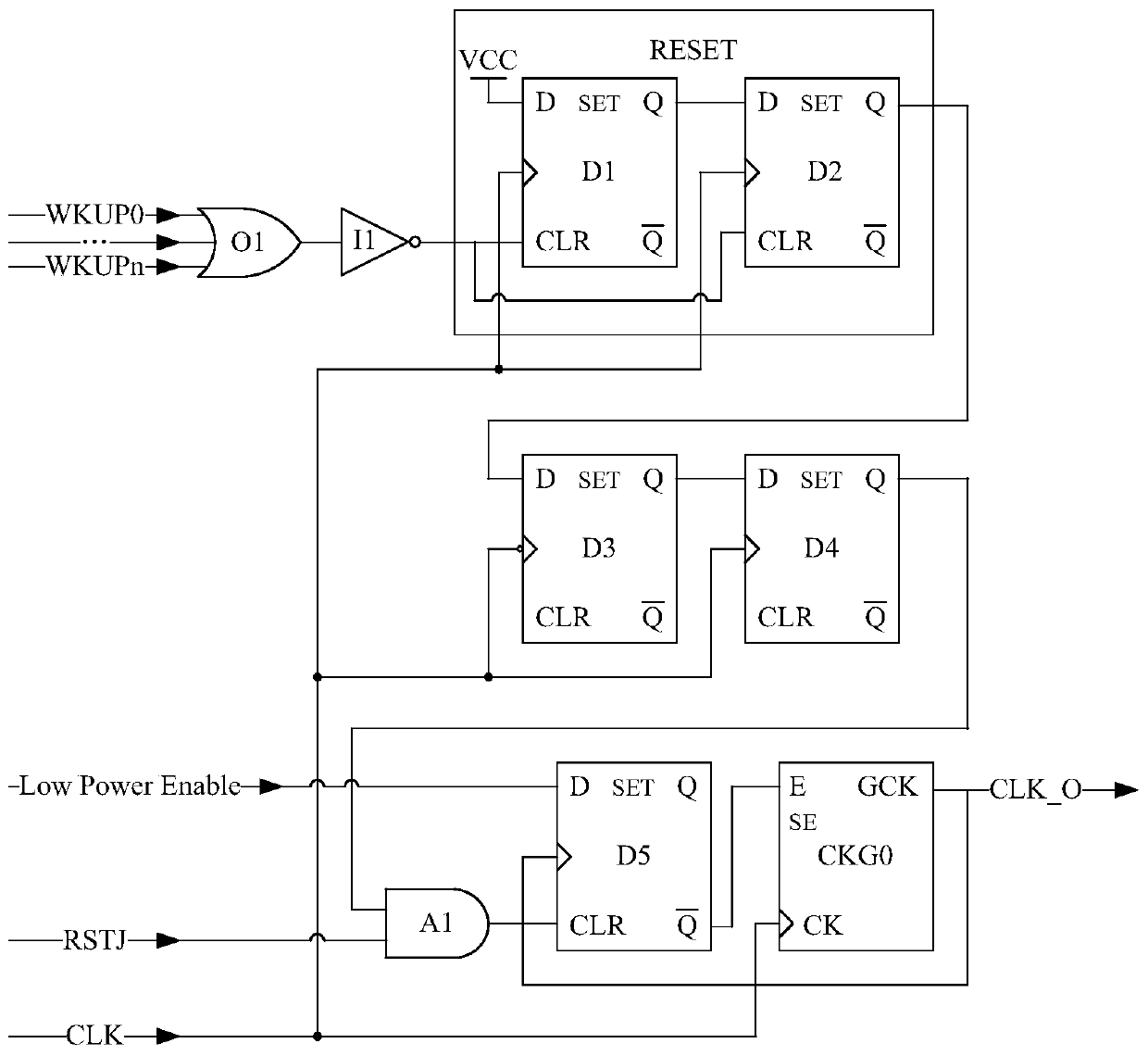
[0028] Specifically, the above-mentioned first register may be a D flip-flop D5, and D5 includes: an input D terminal (that is, the above-mentioned input terminal), a clock CP terminal, a reset CLR terminal, a set SET terminal, an output Q terminal, and an output terminal (that is, the above-mentioned inverting output terminal), wherein, the Q terminal and The terminal is a complementary signal, and the SET terminal o...

Embodiment 2

[0082] According to an embodiment of the present invention, an embodiment of a method for controlling a low-power circuit is provided. It should be noted that the steps shown in the flowcharts of the accompanying drawings can be executed in a computer system such as a set of computer-executable instructions , and, although a logical order is shown in the flowcharts, in some cases the steps shown or described may be performed in an order different from that shown or described herein.

[0083] The above-mentioned low power consumption circuit may be any one of the low power consumption circuits in Embodiment 1.

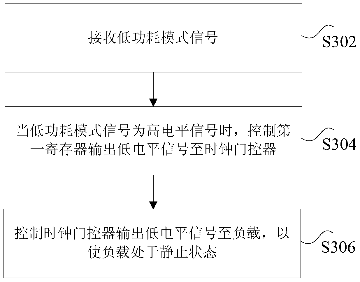
[0084] image 3 is a flowchart of a control method for a low-power circuit according to an embodiment of the present invention, such as image 3 As shown, the method includes the following steps:

[0085] Step S302, receiving a low power consumption mode signal.

[0086] Specifically, the above-mentioned low power consumption mode signal can be the Low Power Enable t...


PUM


Abstract

The invention discloses a low power circuit and control method thereof, wherein the low power circuit comprises a first register, the input end of the first register inputs a low power mode signal, when the low-power mode signal is a high-level signal, the reverse output end of the first register outputs a low-level signal; and a clock gate controller, the clock gate controller is connected to the reverse output end of the first register, the input end of the clock gate controller inputs the clock signal, and the output end of the clock gate controller is connected to the load and the end of clock controller of the first register respectively for outputting the low level signal to the load so that the load is at rest. The low power circuit and control method thereof has the advantages of solving the technical problems that the large dynamic power consumption of a chip inner of portable system in the prior art.

Description

technical field [0001] The invention relates to the field of portable systems, in particular to a low power consumption circuit and a control method thereof. Background technique [0002] The famous law "Moore's Law" in the development of integrated circuits tells that the scale of integration quadruples every three years, which leads to the improvement of performance, and also leads to higher and higher total power consumption, while portable systems powered by batteries have reduced Power consumption becomes critical in circuit design. Therefore, there is a need to quickly reduce the power consumption of the system. [0003] The internal power consumption of the chip is divided into static and dynamic two parts. The static part mainly refers to the leakage current of the transistor, which is mainly determined by the manufacturing process. The smaller the process size, the greater the quiescent current. The dynamic part is mainly divided into two parts: continuous chargi...

Claims


Application Information

Patent Timeline
Patent Type & Authority Patents(China)
IPC IPC(8): G06F1/3237
CPCG06F1/3237
Inventor 刘浩张浩亮温浪明陈恒
Owner GREE ELECTRIC APPLIANCES INC
Why Eureka
Try Eureka