Capacitor discharge sintered metal 3d printer

A 3D printer and capacitive discharge technology, applied in the direction of additive processing, etc., can solve the problems of complex equipment structure, not easy to popularize, complex design, etc.

Inactive Publication Date: 2017-06-09
韩邦伟
View PDF0 Cites 5 Cited by
  • Summary
  • Abstract
  • Description
  • Claims
  • Application Information

AI Technical Summary

Problems solved by technology

[0003] The above printing methods of metal sintering and melting have complex structures, huge mechanisms, low printing efficiency, slow printing sp

Method used


Image

  • Capacitor discharge sintered metal 3d printer
  • Capacitor discharge sintered metal 3d printer
  • Capacitor discharge sintered metal 3d printer

Examples


Embodiment Construction

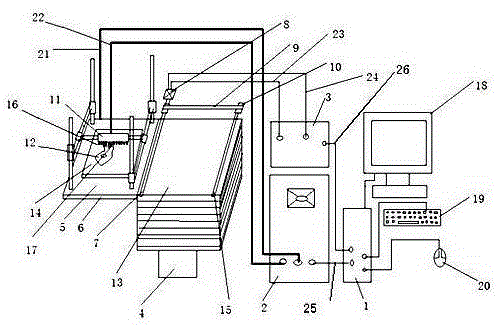
[0017] like figure 1 Capacitive discharge sintering 3D printer shown. Under the control of the control computer (1), send a drive signal to the printer drive power supply (3) through the computer-controlled consumable drive power signal line (26), and the drive power supply passes through the consumable drive motor power line (24) to the idler motor (8) Power is supplied to drive the idler motor to drive the consumable rubber idler (7), and the pulley (10) and the belt (9) drive the consumable passive rubber idler (15). The two printing consumables (13) are transferred to the printing platform (6) of the printing chamber (5) twice by the consumable rubber rollers (7) and (15). The printing chamber can be filled with inert gas for sintering protection. Then the control computer issues instructions to the capacitor discharge sintering power supply (2) according to the layered section information, and the capacitor discharge sintering power supply (21) supplies high-energy elect...


PUM


Abstract

The invention discloses a capacitor discharge metal sintering 3D printer, including a capacitor discharge sintering device that can be used in a metal 3D printer, capacitor charging under the control of a computer, and then the capacitor is selectively discharged under computer control to generate high-temperature arcs and discharge. High-temperature electric arc, sintering the synthesized sheet metal consumables in the printing chamber to form a solid body, and then repeating the last repetition, stacking and sintering to form the device that needs the object, computer-controlled printing chamber mechanism, capacitor discharge welding machine and metal 3D Printer connection.

Description

technical field [0001] The present invention relates to the field of metal rapid prototyping technology or additive manufacturing technology, also called metal 3D printer. Background technique [0002] Existing metal 3D printers include selective laser melting (SLM) technology, selective laser sintering (SLS) technology, direct metal laser sintering (DMLS) technology, electron beam melting (EBM) technology, laser net shape manufacturing (Laser Engineered Net Shaping, LENS) technology. The first three technologies are only different in names and technical details, but they are all similar in principle. Generally, it refers to laying a layer of metal powder-like material on the workbench and heating it until the material is slightly below the melting point, then using a high-energy laser beam to melt the metal powder and fuse it with the previous layer into a solid whole, while The powder material that has not been scanned is still in powder form as the support of the workpi...

Claims


Application Information

Patent Timeline
IPC IPC(8): B22F3/115B33Y30/00
Inventor 韩邦伟
Owner 韩邦伟
Why Eureka
Try Eureka