
Connecting method and system for endless rolled intermediate slabs

A technology of endless rolling and connecting method, applied in the direction of metal rolling, metal rolling, manufacturing tools, etc., can solve the problems of high equipment investment and maintenance cost, low connection strength of intermediate billets, influence of strength of connection area, etc. Achieve the effect of improving the mechanical properties of the joint, shortening the welding time, simplifying the process and equipment

Active Publication Date: 2017-06-09
CISDI ENG CO LTD
View PDF4 Cites 6 Cited by
  • Summary
  • Abstract
  • Description
  • Claims
  • Application Information

AI Technical Summary

Problems solved by technology

This connection method is mainly suitable for the connection of the same material because it applies pressure to the shear surface for physical connection. When different materials are connected, the strength of the connection area is also affected due to the difference in chemical composition and physical metallurgical properties. At the same time, The equipment is huge, takes up a lot of space, equipment investment and maintenance costs are high, etc.
[0009] In a word, the connection methods of intermediate blanks in the prior art all have one of the problems of large equipment investment, low connection strength of intermediate blanks, slow connection speed, not suitable for connection of dissimilar steel materials, huge equipment, and high maintenance costs. or several

Method used


Image

  • Connecting method and system for endless rolled intermediate slabs
  • Connecting method and system for endless rolled intermediate slabs
  • Connecting method and system for endless rolled intermediate slabs

Examples


Embodiment 1

[0065] In this example, the front-back direction is the rolling direction as the front.

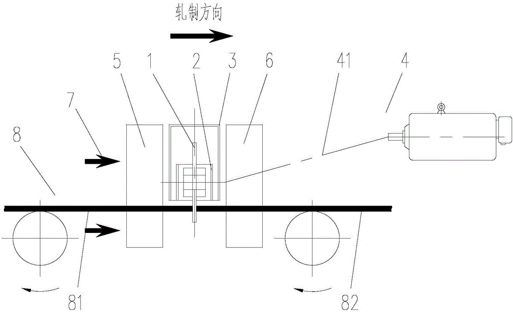
[0066] The invention provides a method for connecting intermediate blanks. Specifically, the head and tail ends of the front and rear intermediate blanks are aligned, and the tail end face of the front intermediate blank and the head end face of the rear intermediate blank are rubbed. The forward frictional pressure is exerted on the middle billet, so that the connecting end face and the surrounding area of ​​the front and rear middle billets rapidly heat up to a viscoplastic state, and the head of the rear middle billet is connected forward with the tail of the front middle billet Together. The friction method can be rotational friction or vibration friction.

[0067] Using the solid state welding method, the material to be welded does not melt, the metal in the welding zone is forged structure, and there is no defect of melting welding; under the action of upsetting force, some mechani...

Embodiment 2

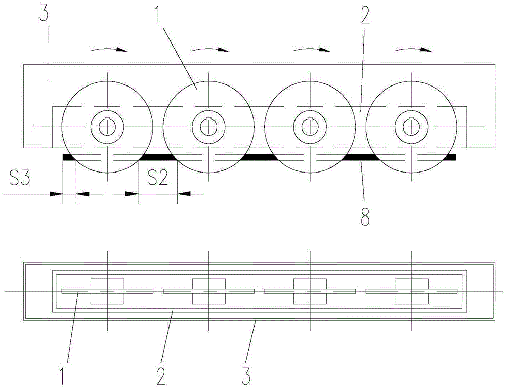
[0077] The difference between this example and Embodiment 1 is that the structure of the intermediate blank connecting device 500 is different, such as Image 6 with Figure 7 As shown, this example adopts the mode of vibration friction, that is, the friction mechanism 1 is a friction blade, and also includes a friction blade vibrating tool holder 91, a friction blade pressing tool holder 92, a friction blade vibration device 93, an inlet clamping device 5, an outlet clamp Holding device 6 and upsetting device 7. The inlet clamping device 5, the outlet clamping device 6 and the upsetting device 7 are the same as those in the first embodiment.

[0078] Wherein, the entrance clamping device 5 is used for clamping the rear block intermediate blank 81, and the outlet clamping device 6 is used for clamping the front block intermediate blank 82, and the friction blade is installed on the friction blade vibrating knife rest 91, and the friction blade vibrating knife rest 91 Install...


PUM


Abstract

The invention provides a connecting method for endless rolled intermediate slabs. The method comprises the following steps: aligning the head and tail end portions of front and back intermediate slabs; rubbing the tail portion end surface of the front intermediate slab and the head portion end surface of the back intermediate slab; applying a forward force to the back intermediate slab in the rubbing period; and when the temperature of the connecting end surface of the front and back intermediate slabs is raised to a viscoplastic state, connecting the head of the back intermediate slab forward together with the tail portion of the front intermediate slab under the action of an upsetting force. The method provided by the invention is high in connecting strength, fast in connecting speed and low in energy consumption and is suitable for connecting slabs made from different materials.

Description

technical field [0001] The invention belongs to the field of hot rolling equipment, and relates to a method and system for connecting intermediate blanks in the process of converting conventional hot rolling into endless rolling in the iron and steel industry. Background technique [0002] The production of traditional strip hot continuous rolling finishing mills is carried out with a single intermediate billet for rolling, and entering the finishing mill generally goes through processes such as strip threading, accelerated rolling, decelerated rolling, steel throwing, and tail flicking. In the process of finishing rolling, especially in thin-gauge rolling, it is easy to bite into the head of the strip between the finishing stands and be blocked, forming piles of steel, slipping and tail flick folding, and tail flicking forms fold bite, resulting in damage to the roll surface etc.; during coiling, due to the serpentine shape and bending of the front end of the strip, the coi...

Claims


Application Information

Patent Timeline
Patent Type & Authority Applications(China)
IPC IPC(8): B23K20/12B21B1/26B21B15/00
CPCB21B1/26B21B15/0085B23K20/12B23K20/122B23K20/1245
Inventor 刘玉堂杨春楣韩会全
Owner CISDI ENG CO LTD
Learn More