
Oil mist removing device for machine tool

A technology of oil mist and machine tools, which is applied in the field of machinery, can solve problems such as poor practicability, and achieve the effects of improving filtering effect, improving convenience, and improving work stability

Inactive Publication Date: 2017-06-09
天津市华洋鑫福金属制品有限公司
View PDF1 Cites 0 Cited by
  • Summary
  • Abstract
  • Description
  • Claims
  • Application Information

AI Technical Summary

Problems solved by technology

But there is still a problem in this oil mist suction device: because the height of the casing and the angle of the air inlet of the casing are fixed, the device is adapted according to machine tools with different characteristics, resulting in the practicality of the device. Poor sex

Method used


Image

  • Oil mist removing device for machine tool
  • Oil mist removing device for machine tool

Examples


Embodiment 1

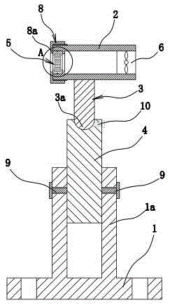
[0024] Such as figure 1 As shown, the oil mist removal device for the machine tool is composed of a base 1, a support cylinder 2, a hinged rod 3, a connecting column 4, a filter screen 5, an exhaust fan 6, and the like.

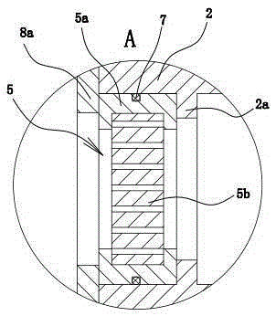
[0025] Wherein, the support cylinder 2 is cylindrical and arranged along the horizontal direction. The suction fan 6 is fixed inside one end of the support cylinder 2 , and the filter screen 5 is fixed inside the other end of the support cylinder 2 . In this example, if figure 1 and figure 2 As shown, the filter screen 5 includes an annular connecting ring 5 and a filter screen 5b fixed in the connecting ring 5 . Wherein, the outer wall of the connecting ring 5 is provided with an annular groove, and an O-shaped sealing ring 7 is arranged in the annular groove, and the outer peripheral surface of the O-shaped sealing ring 7 is against the inner wall of the supporting cylinder 2, so that the connecting ring 5 A more reliable seal is formed between the sup...

Embodiment 2

[0031] The structure and principle of this second embodiment are basically the same as that of the first embodiment, except that the locking mechanism includes a threaded hole three penetrating through the side wall of the connecting part 1a, a threaded hole four and a screw threaded on the side wall of the connecting column 4 There are several bolts 3 and 4 connected in the threaded holes 3 and they are evenly distributed along the axial direction of the connection part 1a, and the end of the bolts 3 is screwed into one of the threaded holes 4.


PUM


Abstract

The invention provides an oil mist removing device for a machine tool, belongs to the technical field of machinery, and solves the problem that the conventional oil mist sucking device of the numerically-controlled machine tool is poor in practicality. The oil mist removing device for the machine tool comprises a supporting barrel, and a filter screen and an exhaust fan which are fixedly arranged inside the two ends of the supporting barrel respectively, wherein a base is arranged below the supporting barrel; a cylindrical connecting part is arranged on the base; a hinge rod is fixed to the side wall of the supporting barrel; a connecting column is vertically arranged between the connecting part and the hinge rod; the lower end of the connecting column is inserted into the connecting part; a locking mechanism for preventing relative sliding is arranged between the connecting column and the connecting part; the lower end of the hinge rod adopts a hemispherical ball head; a hemispherical groove is formed in the upper end surface of the connecting column; the ball head is accommodated inside the groove; a threaded hole 1 communicated with the groove is formed in the side wall of the connecting column along the radial direction of the connecting part; a bolt 1 is screwed inside the threaded hole 1; the end part of the bolt 1 is tightly pressed against the side wall of the ball head. The oil mist removing device for the machine tool has the advantage of high practicality.

Description

technical field [0001] The invention belongs to the technical field of machinery, and relates to a machine tool, in particular to an oil mist removal device for a machine tool. Background technique [0002] Existing CNC machine tools will generate a large amount of heat during high-speed cutting, causing the cutting fluid and cooling fluid to be heated and evaporated, and the evaporated cutting fluid and cooling fluid will form a large amount of floating oil mist, which will not only It will affect the life of the machine tool, and will cause environmental pollution and affect the health of the staff. [0003] For this situation, people have realized this deficiency and made improvements, such as a kind of oil mist suction device for CNC machine tools [application number: 201320243051.8; announcement number: CN 203264481 U] disclosed in Chinese patent documents, including A casing, the casing is provided with an air inlet and an exhaust port, a negative pressure fan is arra...

Claims


Application Information

Patent Timeline
Patent Type & Authority Applications(China)
IPC IPC(8): B23Q11/00B01D46/10B08B15/04
CPCB23Q11/00B01D46/10B08B15/04
Inventor 杨庆婷
Owner 天津市华洋鑫福金属制品有限公司
Learn More