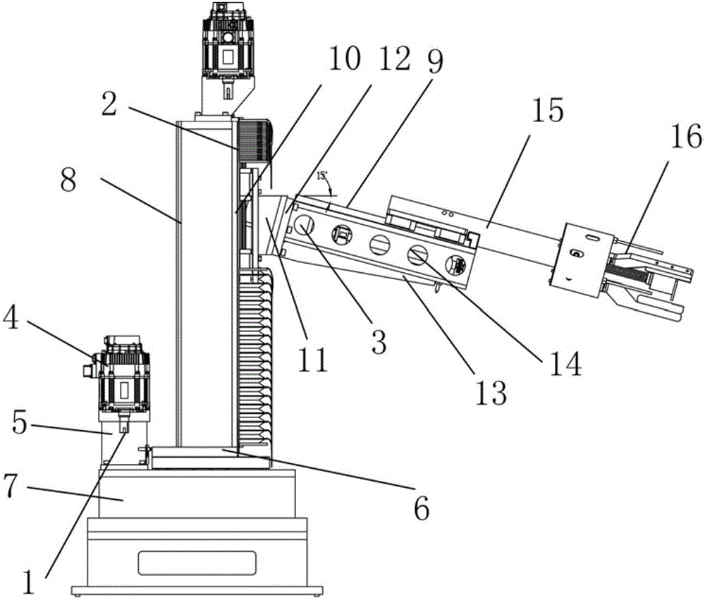
Layout structure of three-shaft linkage mechanical hand
A three-axis linkage, layout structure technology, applied in manipulators, program-controlled manipulators, manufacturing tools, etc., can solve the problems of low work efficiency, large action distance, long action cycle, etc., to achieve compact structure, short action cycle, and action stroke. small effect
- Summary
- Abstract
- Description
- Claims
- Application Information
AI Technical Summary
Problems solved by technology
Method used
Image
Examples
Embodiment
[0018] like figure 1 As shown, a layout structure of a three-axis linkage manipulator includes a rotating C-axis 1, a linear Z-axis 2, a linear X-axis 3, a motor 4, a reducer 5, a rotary table 6, a C-axis reducer 7, a column 8, a linear Guide rail 9, secondary transmission conversion lead screw 10, arm connecting block 11, arm system 12, arm bracket 13, rear arm 14, forearm 15, pawl 16.
[0019] Firstly, the rotating C-axis 1 is arranged, and the C-axis reduction box 7 is arranged on the rotating C-axis 1 , and then the motor 4 , the reduction gear 5 and the rotary table 6 are arranged on the C-axis reduction box 7 . On the turntable 6, a linear Z-axis 2 and a column 8 are arranged, and a motor 4 of a linear Z-axis 2, a speed reducer 5, a linear guide rail 9 and an auxiliary transmission conversion leading screw 10 are arranged on the column 8.
[0020] Then lay out the linear X-axis 3 , set the motor 4 of the linear X-axis 3 , the linear guide rail 9 , the secondary transmis...
PUM
 Abstract
Description
Claims
Application Information
 - R&D
- Intellectual Property
- Life Sciences
- Materials
- Tech Scout
- Unparalleled Data Quality
- Higher Quality Content
- 60% Fewer Hallucinations
Browse by: Latest US Patents, China's latest patents, Technical Efficacy Thesaurus, Application Domain, Technology Topic, Popular Technical Reports.
© 2025 PatSnap. All rights reserved.Legal|Privacy policy|Modern Slavery Act Transparency Statement|Sitemap|About US| Contact US: help@patsnap.com

