Molecular distillation separation method for grease chemical product and equipment

A molecular distillation and oleochemical technology, applied in molecular distillation, fat oil/fat refining, fat production, etc., can solve the problem that the heat conduction oil chamber is easy to protrude and break into the oil chamber, the distillation and evaporation effect is not good, and the main equipment is not scientific and other issues, to achieve the effects of saving power resources, good sealing effect, low equipment manufacturing and operation and maintenance costs

Inactive Publication Date: 2017-06-09
饶攀
View PDF3 Cites 13 Cited by
  • Summary
  • Abstract
  • Description
  • Claims
  • Application Information

AI Technical Summary

Problems solved by technology

However, there are certain limitations in this technique:
[0005] 1. The design body of the equipment has an oil cavity and a heat transfer oil cavity. The oil cavity is negative pressure, and the heat transfer oil cavity is positive pressure. If it goes into the oil cavity, the consequences will be unimaginable. At the same time, because the heating surface is not round and evenly stressed, it is also easily deformed, and the distillation and evaporation effect is not good.
[0006] 2. The oil chamber of this technology has chamber A on the top and chamber B below, which is equivalent to an oil storage tank with an oil storage function on the top and an oil storage tank with an oil storage function on the bottom. Such a main body The equipment is not scientific

Method used


Image

  • Molecular distillation separation method for grease chemical product and equipment
  • Molecular distillation separation method for grease chemical product and equipment
  • Molecular distillation separation method for grease chemical product and equipment

Examples


Embodiment 1

[0053] A molecular distillation and separation device for oleochemical products, which includes a molecular distillation device body 1 and a vacuum tube 6, and the cross section of the molecular distillation device body 1 is a semicircular or semielliptical hollow cylinder.

[0054] The material heating panel of the molecular distillation equipment body 1 is a rectangular side plane of a hollow cylinder, and a heating medium coil is welded close to the back; there is a material distribution pipe 15 on the top of the heating surface, and the material distribution is composed of a material distribution groove plate 8 There is a material redistribution tank composed of a material redistribution tank plate 7 in the middle of the tank; the bottom end of the arc surface of the molecular distillation equipment body 1 is connected to the vacuum tube 6, and the molecular distillation equipment body 1 has a material feeding tube 2 on it, and a material outlet tube 3 on the bottom ; Molec...

Embodiment 2

[0058] A molecular distillation and separation device for oleochemical products, which includes a molecular distillation device body 1 and a vacuum tube 6, and the cross section of the molecular distillation device body 1 is a semicircular or semielliptical hollow cylinder.

[0059] The material heating panel of the molecular distillation equipment body 1 is a rectangular side plane of a hollow cylinder, and a heating medium coil is welded close to the back; there is a material distribution pipe 15 on the top of the heating surface, and there is a material distribution groove composed of a material distribution groove plate 8. The middle part has a material redistribution tank composed of a material redistribution tank plate 7; the bottom end of the arc surface of the molecular distillation equipment body 1 is connected to the vacuum tube 6, and the molecular distillation equipment body 1 has a material feeding tube 2 and a material outlet tube 3 under it.

[0060] The inner ca...

Embodiment 3

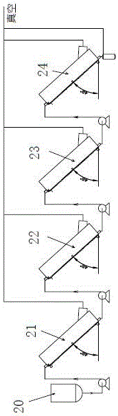
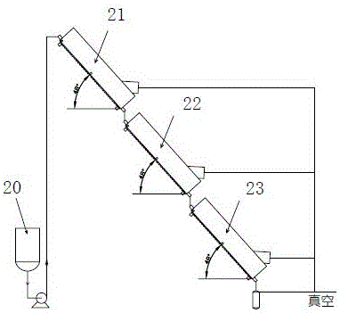
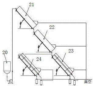
[0066] The molecular distillation and separation equipment for oleochemical products can be used individually, or multiple devices can be used in series and / or in parallel, and the separation and purification effect is better.

[0067] Such as figure 1 As shown in -3, the oily product in the oily product storage tank 20 passes through the first stage 21 of the molecular still. , evenly distributed on the heating surface, forming a uniform film that flows from top to bottom, flows to the middle material redistribution channel plate 7, and distributes evenly again, and the low boiling point oily product evaporates under the action of heating and vacuum Take away in vacuum, the remaining high-boiling point oily products are collected into the material outlet pipe 3, flow out of the first stage 21 of the molecular still, enter the second stage 22 of the molecular still, and so on, enter the third stage 23 of the molecular still, and the fourth stage of the molecular still twenty ...


PUM


Abstract

The invention discloses a molecular distillation separation method for a grease chemical product and equipment. A molecular distillation system consists of single molecular distillation equipment or multi-stage molecular distillation equipment in manners of serial connection, parallel connection or combination of serial connection and parallel connection; the multi-stage molecular distillation equipment is arranged in horizontal positions, up and down positions or combined way of horizontal positions and up and down positions; a product to be distilled is fed into the molecular distillation equipment from the top, is uniformly allocated for a first time through allocation tube holes or/and groove plates, is uniformly distributed to the upper part of a heating surface of the equipment to form a uniform film flowing from top to bottom, and is at least uniformly allocated further for a second time through an allocation groove plate or screening holes, and is uniformly distributed to the bottom from the heating surface of the equipment; under the action of heating and vacuum, a low-melting point oil chemical product is evaporated and recycled as a product of a first-class type; a high-melting point oil chemical product is fed to a next stage of molecular distillation; temperature and vacuum degrees of different stages of the molecular distillation equipment are determined according to low-melting point oil chemical products to be removed in equipment of a same stage, and various types of high-quality products can be prepared finally.

Description

technical field [0001] The invention belongs to the technical field of oleochemical products, and in particular relates to a method for distillation, purification and separation of different components of oleochemical products, other various chemical products, and plant extracts, in particular to a molecular distillation separation of oleochemical products Methods and equipment. Background technique [0002] At present, manufacturers of oleochemical products mainly use rising film and falling film evaporative distillation methods. These rising film and falling film evaporative distillation methods have several disadvantages. One is that the evaporation efficiency is not high, and the final material distillation residue is large. A material circulation pump is installed outside the distillation tower to heat the material repeatedly, so that the material produces new polymers. The third is that the evaporation and distillation time is long and the temperature is high, which ha...

Claims


Application Information

Patent Timeline
Patent Type & Authority Applications(China)
IPC IPC(8): C11B3/12B01D3/12
CPCB01D3/12C11B3/12
Inventor 饶攀饶燕李抗饶雨农
Owner 饶攀
Why Eureka
Try Eureka