
Longitudinal-rib-above-arranged steel-concrete-steel-shell-combining-beam cable-stayed bridge

A top-mounted, cable-stayed bridge technology, applied to cable-stayed bridges, bridges, bridge parts, etc., can solve the problems of complex design and construction of the steel-concrete transition section of mixed-girder cable-stayed bridges, a large number of welds, and slow construction speed , to achieve the effect of being conducive to track stability, improving durability and reducing self-weight

Active Publication Date: 2017-06-09
CHINA RAILWAY SIYUAN SURVEY & DESIGN GRP
View PDF8 Cites 7 Cited by
  • Summary
  • Abstract
  • Description
  • Claims
  • Application Information

AI Technical Summary

Problems solved by technology

[0004] 2. There are many vertical and horizontal welds on the deck of the steel box girder orthogonal special-shaped slab, the stress is complex, and fatigue cracks are prone to occur;
[0005] 3. For conventional steel box composite girder bridges, the concrete bridge deck needs to be equipped with a cast-in-place construction formwork system; if prefabricated construction is used, a concrete post-cast belt needs to be set up, and the construction speed is slightly slower
[0007] 5. The design and construction of the steel-concrete transition section of the hybrid girder cable-stayed bridge is complicated

Method used


Image

  • Longitudinal-rib-above-arranged steel-concrete-steel-shell-combining-beam cable-stayed bridge
  • Longitudinal-rib-above-arranged steel-concrete-steel-shell-combining-beam cable-stayed bridge
  • Longitudinal-rib-above-arranged steel-concrete-steel-shell-combining-beam cable-stayed bridge

Examples


Embodiment Construction

[0031] The present invention will be further described in detail below in conjunction with the accompanying drawings and specific embodiments.

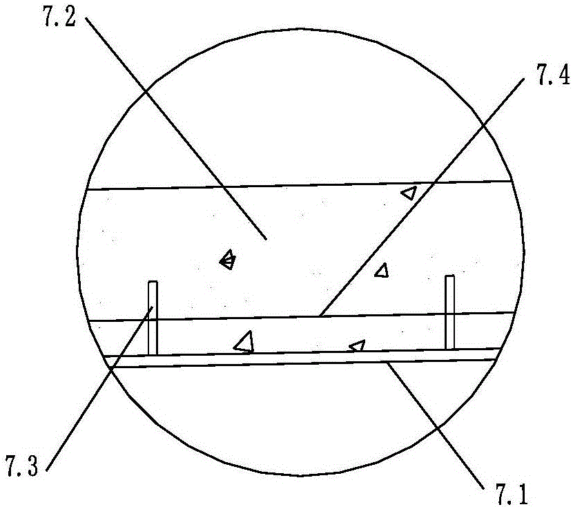
[0032] As shown in Fig. 1, a cable-stayed bridge with longitudinal ribs above the steel-concrete steel shell combined girders includes the main girder 1 of the cable-stayed bridge. The side span 3 and the transition section 4 arranged between the main span 2 and the side span 3 are composed. The two sides of the main girder 1 of the cable-stayed bridge in the length direction are provided with main towers 5 vertically arranged at intervals, and each main tower 5 The top of the cable-stayed bridge and the main girder 1 of the cable-stayed bridge are fixedly connected by several stay cables 6, the main span 2 is a steel-concrete composite integral steel box girder structure, and the side span 3 is a steel-concrete composite steel shell concrete beam structure.

[0033] Such as figure 2 and image 3As shown, the steel-concrete composi...


PUM


Abstract

The invention discloses a longitudinal-rib-above-arranged steel-concrete-steel-shell-combining-beam cable-stayed bridge. The longitudinal-rib-above-arranged steel-concrete-steel-shell-combining-beam cable-stayed bridge comprises a main cable-stayed-bridge beam, the main cable-stayed-bridge beam is composed of a main span, side spans arranged on the two sides of the main span and transition sections arranged between the main span and the side spans; main towers are arranged on the two sides in the length direction of the main cable-stayed-bridge beam at intervals, wherein the main towers and the main cable-stayed-bridge beam are perpendicularly arranged; the tops of all the main towers are fixedly connected with the main cable-stayed-bridge beam through a plurality of stay cables, the main span is of a steel-concrete-combination whole steel box beam structure, and the side spans are of steel-concrete-combination-steel-shell-concrete-beam structures. According to the longitudinal-rib-above-arranged steel-concrete-steel-shell-combining-beam cable-stayed bridge, a longitudinal-rib-above-arranged steel-concrete-combination whole steel box beam is used for the main span, longitudinal-rib-above-arranged steel shell concrete beams are used in the side spans, bran-new steel concrete transition section modes are designed for the side spans, the large spanning capacity and the vertical rigidity are achieved, the construction speed is high, it is avoided that negative reaction force of the side spans appear, and the service life of the bridge face is prolonged.

Description

technical field [0001] The invention belongs to the technical field of cable-stayed bridges, in particular to a cable-stayed bridge with upper longitudinal ribs and steel-mixed steel shell combined girders. Background technique [0002] The advantages of conventional steel box girder cable-stayed bridges are light weight, large spanning capacity, steel box girders can be manufactured in factories, reliable quality, and fast construction speed; steel box composite girder cable-stayed bridges use less steel and the main bridge rigidity Large; hybrid girder cable-stayed bridges are economical and rigid. The above three cable-stayed bridges all have the following deficiencies in the application process: [0003] 1. Steel box girder cable-stayed bridge, the main girder has light weight, the main girder anchorage support effect is small, and the overall stiffness of the main bridge is relatively small; [0004] 2. There are many vertical and horizontal welds on the deck of the s...

Claims


Application Information

Patent Timeline
IPC IPC(8): E01D11/04E01D19/00
CPCE01D11/04E01D19/00
Inventor 刘振标崔苗苗薛照钧陈勇罗春林史娣尹书军王鹏宇
Owner CHINA RAILWAY SIYUAN SURVEY & DESIGN GRP
Learn More