Eureka AIR delivers breakthrough ideas for toughest innovation challenges, trusted by R&D personnel around the world.

Method for mounting metal plate cylinder

An installation method and metal plate technology, applied in the direction of columns, pier columns, pillars, etc., can solve the problems of stainless steel columns without a good installation method, difficult construction, rough manufacturing process, etc.

Active Publication Date: 2017-06-09
中建八局装饰工程有限公司
View PDF9 Cites 4 Cited by
  • Summary
  • Abstract
  • Description
  • Claims
  • Application Information

AI Technical Summary

Problems solved by technology

[0002] At present, there is no good installation method for super large stainless steel columns, the production process is rough, the construction is difficult, and it is difficult to realize its installation

Method used


Image

  • Method for mounting metal plate cylinder
  • Method for mounting metal plate cylinder
  • Method for mounting metal plate cylinder

Examples


Embodiment

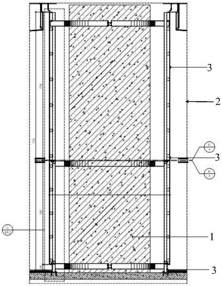
[0033] figure 1 It is an elevational cross-sectional view of the metal plate cylinder in the embodiment of the present invention.

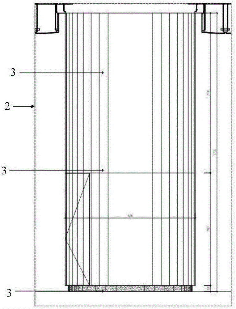
[0034] figure 2 It is an elevation view of the metal plate cylinder in the embodiment of the present invention.

[0035] Such as figure 1 with figure 2 As shown, the structural column of the metal plate cylinder is a steel structure column 1, and the surface layer is a fireproof coating 2. When the metal plate cylinder is used, no welding can be adopted to the original structural column, and a hoop bolting method is adopted.

[0036] The curved stainless steel panel 3 is formed by the arc radius on the roller arc machine. In order to make the horizontal seam of the curved stainless steel panel 3 beautiful, the curved stainless steel panel 3 has a small hemming R angle, and the curved stainless steel panel 3 is performed at the left and right sides and the upper and lower sides. Gouging treatment, the gouging depth is 70 threads, the upper and lower fol...


PUM


Abstract

The invention provides a method for mounting a metal plate cylinder. The method is characterized by comprising the following steps: A, measuring and setting out; B, mounting an arc-shaped hoop steel plate; C, welding a vertical main keel; D, mounting a transverse secondary keel; E, performing corrosion-resistant and anti-rust treatment; F, mounting an arc-shaped stainless steel panel; G, fixing a steel plug pin in a stainless steel flange on the edge of the plate; H, fixing angle codes as well as the vertical main keel and the transverse secondary keel; I, mounting a U-shaped stainless steel clamping strip; J, mounting a skirting line.

Description

Technical field [0001] The invention relates to an installation method, in particular to an installation method of a metal plate cylinder. Background technique [0002] At present, there is no good installation method for the super large stainless steel column, the production process is rough, the construction is difficult, and it is difficult to realize its installation. Summary of the invention [0003] The present invention is made to solve the above-mentioned problems, and aims to provide a method for installing a metal plate cylinder that does not require welding and has a fine manufacturing process. [0004] The method for installing a metal plate cylinder provided by the present invention has such characteristics and includes the following steps: [0005] Step A, measure and pay off; [0006] Step B, installation of arc-shaped hoop steel plate; [0007] Step C, welding the vertical main keel; [0008] Step D, horizontal secondary keel installation; [0009] Step E, anti-corrosion ...

Claims


Application Information

Patent Timeline
IPC IPC(8): E04C3/32
CPCE04C3/32
Inventor 周亮刘振永孙宁
Owner 中建八局装饰工程有限公司
Why Eureka
Eureka Blog
Learn More