Multilateral Wire Saw Cutting Machine
A cutting machine and wire saw technology, which is applied in the field of multilateral wire saw cutting machines, can solve the problems of simultaneous cutting of multiple sides of stone materials and slow stone cutting efficiency of wire saw cutting machines, so as to reduce the probability of safety accidents, improve cutting efficiency, and improve The effect of horizontal stability
- Summary
- Abstract
- Description
- Claims
- Application Information
AI Technical Summary
Problems solved by technology
Method used
Image
Examples
Embodiment 1
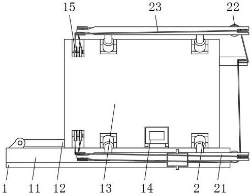
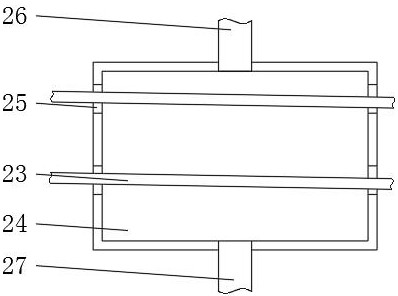
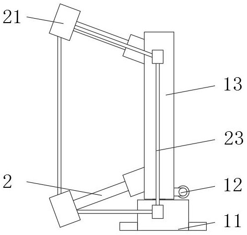
[0026] Embodiment 1: A polygonal wire saw cutting machine, including an adjustment plate 1, a push rod body 2, a transport cart 3, a frame body 13, a cutting rope 23 and a connecting cover 24, and a slide is installed on one side of the outer wall of the upper end of the adjustment plate 1. Seat 11, the frame body 13 is slidingly installed on one side of the outer wall of the upper end of the sliding seat 11, the push rod body 2 distributed in a rectangular array is installed on the outer wall of the frame body 13 side, and the cutting rod 21 is installed on the outer wall of the push rod body 2 side. The outer walls of both sides of the frame body 13 away from the push rod body 2 are provided with guide wheels 15, the outer walls of one side of the guide wheels 15 are sleeved with a cutting rope 23, and the outer walls of the lower end of the adjustment plate 1 are provided with a transport cart 3, and the outer walls of the upper end of the transport cart 3 are symmetrical. T...
Embodiment 2
[0029]Embodiment 2: A polygonal wire saw cutting machine, including an adjustment plate 1, a push rod body 2, a transport vehicle 3, a frame body 13, a cutting rope 23 and a connecting cover 24, and a slide is installed on one side of the outer wall of the upper end of the adjustment plate 1. Seat 11, the frame body 13 is slidingly installed on one side of the outer wall of the upper end of the sliding seat 11, the push rod body 2 distributed in a rectangular array is installed on the outer wall of the frame body 13 side, and the cutting rod 21 is installed on the outer wall of the push rod body 2 side. The outer walls of both sides of the frame body 13 away from the push rod body 2 are provided with guide wheels 15 , and a cutting rope 23 is sleeved on the outer walls of one side of the guide wheels 15 .
[0030] Sliding seat 11 is away from frame body 13 side outer walls and is equipped with push cylinder 12, and supporting leg 31, push cylinder 12 and push rod body 2 all ado...
Embodiment 3
[0035] Embodiment 3: A multilateral wire saw cutting machine, including an adjustment plate 1, a push rod body 2, a transport vehicle 3, a frame body 13, a cutting rope 23 and a connecting cover 24, and a sliding seat is installed on the outer wall side of the upper end of the adjustment plate 1 11. A frame body 13 is slidably installed on one side of the outer wall of the upper end of the sliding seat 11, and a push rod body 2 distributed in a rectangular array is installed on one side of the outer wall of the frame body 13, and a cutting rod 21 is installed on one side of the outer wall of the push rod body 2. Body 13 deviates from push rod body 2 both sides outer walls are provided with guide wheels 15, guide wheels 15 side outer wall is sleeved with cutting rope 23, adjustment plate 1 lower end outer wall side is provided with transport cart 3, transport cart 3 both sides outer walls are A fixed plate 4 is installed symmetrically, a first oil cylinder 41 is installed on one...
PUM
 Abstract
Description
Claims
Application Information
 - R&D
- Intellectual Property
- Life Sciences
- Materials
- Tech Scout
- Unparalleled Data Quality
- Higher Quality Content
- 60% Fewer Hallucinations
Browse by: Latest US Patents, China's latest patents, Technical Efficacy Thesaurus, Application Domain, Technology Topic, Popular Technical Reports.
© 2025 PatSnap. All rights reserved.Legal|Privacy policy|Modern Slavery Act Transparency Statement|Sitemap|About US| Contact US: help@patsnap.com


