Wellhead gas injection device

A gas injection and outlet end technology, which is applied in vibration generating devices, wellbore/well components, and production fluids, etc., and can solve the problems of nitrogen production equipment that needs to run at full load for a long time, poor sound wave effect, and high oil consumption.

Inactive Publication Date: 2017-06-09
PUYANG WANGLIAN MACHINERY EQUIP CO LTD
View PDF0 Cites 0 Cited by
  • Summary
  • Abstract
  • Description
  • Claims
  • Application Information

AI Technical Summary

Problems solved by technology

[0003] The purpose of the present invention is to provide a wellhead gas injection device to overcome the defects in the prior art that the sound wave effect is poor when the nitrogen flow rate is low, the nitrogen making equipment needs to be fully loaded and run for a long time, and the oil consumption is high

Method used


Image

  • Wellhead gas injection device

Examples


Embodiment Construction

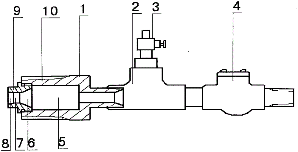
[0010] Such as figure 1 As shown, the present invention includes a combined gas injection joint 1, an equal-diameter tee 2, a vent valve 3, and a check valve 4, wherein the check valve 4, the equal-diameter tee 2, and the combined air injection joint 1 follow the direction of gas injection The vent valve 3 is installed on the equal-diameter tee 2; the combined gas injection joint 1 is composed of a gas injection joint 10 and a nozzle 9. One end of the combined gas injection joint 1 can be connected to the wellhead, and the other end can be connected to the wellhead. The equal diameter tee 2 is connected; there is a cylindrical oscillation chamber 5 inside the gas injection joint 10, and the outlet end of the cylindrical oscillation chamber 5 is firmly connected with the inlet end of the nozzle 9; the interior of the nozzle 9 is sequentially There are conical drainage cavity 6, cylindrical throat 7 and conical feedback cavity 8.

[0011] The outlet end of the cylindrical oscil...


PUM


Abstract

The invention belongs to the technical field of oil and gas exploitation, and relates to a wellhead gas injection device. The invention includes a combined gas injection joint, an equal-diameter tee, a vent valve, and a check valve, wherein the check valve, the equal-diameter tee, and the combined gas injection joint are fixedly connected in sequence according to the gas injection direction, and the vent valve is installed on the equal-diameter Above the tee; the combined gas injection joint is composed of a gas injection joint and a nozzle, one end of the combined gas injection joint can be connected to the wellhead, and the other end can be connected to the equal-diameter tee; there is a cylindrical vibration in the gas injection joint The outlet end of the cylindrical oscillating cavity is firmly connected with the inlet end of the nozzle; inside the nozzle there are a conical drainage cavity, a cylindrical throat and a conical feedback cavity in sequence according to the gas injection direction. The invention overcomes the defects in the prior art that the sound wave effect is poor when the nitrogen flow rate is low, the nitrogen making equipment needs to run at full load for a long time, and the fuel consumption is high.

Description

technical field [0001] The invention belongs to the technical field of oil and gas exploitation, and in particular relates to a wellhead gas injection device. Background technique [0002] When the device was used on site, it was found that when the displacement of injected nitrogen gas was small, the effect of generating sound waves in the gas injection joint was not obvious, the speed of gas lift and liquid discharge was not accelerated, and the gas lift operation took a long time. In order to achieve the purpose of quickly draining the liquid in the well, it is necessary to increase the displacement of injected nitrogen to take advantage of the advantages of sonic gas injection, but the nitrogen production equipment must be in full-load operation, and the nitrogen production equipment consumes more oil. At the same time, construction workers are exposed to high-pressure working environment for a long time, which is not conducive to safe production. Contents of the inven...

Claims


Application Information

Patent Timeline
Patent Type & Authority Applications(China)
IPC IPC(8): E21B43/25E21B43/12E21B28/00
CPCE21B43/255E21B28/00E21B43/122
Inventor 郭玉芳
Owner PUYANG WANGLIAN MACHINERY EQUIP CO LTD
Why Eureka
Try Eureka