
Automatic resistor decapping production line

An assembly line and resistance technology, applied in resistors, resistance manufacturing, circuits and other directions, can solve the problems of low efficiency, entering between the fixed drum and the movable drum, and the size of the non-conformity, and achieve high cap removal efficiency, efficient cap removal, and simple structure. Effect

Active Publication Date: 2017-06-09
山东润蒙应急救援装备有限公司
View PDF1 Cites 1 Cited by
  • Summary
  • Abstract
  • Description
  • Claims
  • Application Information

AI Technical Summary

Problems solved by technology

[0002] At present, in the production of resistors, it is necessary to use a capping machine to add caps to both ends of the resistor blank. Due to the failure of the capping machine or the discrepancy between the size of the resistor blank and the metal cap, it often results in the metal on one or both ends of the resistor blank. The cap is not installed firmly or falls off, resulting in defective products
One is discarding, the resistor body cannot be reused, resulting in a waste of resources and increasing the production cost of the enterprise; the other is manual removal of the cap, which is labor intensive and inefficient
[0003] The Chinese patent has announced a resistance capping machine whose notification number is CN101950649B, which can automatically decap the resistance and realize the reuse of the resistance body. However, the design has the following defects: 1. When the resistance is poured into the feed port The posture is uncertain, and the resistor may enter between the fixed roller and the movable roller in an inclined posture, thereby increasing the difficulty of uncapping; 2. There are no mutual isolation measures during the process of uncapping the resistor, which may cause the gap between adjacent resistors. Squeeze each other, damage the resistor and increase the difficulty of removing the cap

Method used


Image

  • Automatic resistor decapping production line
  • Automatic resistor decapping production line
  • Automatic resistor decapping production line

Examples


Embodiment Construction

[0033] In order to make the technical means, creative features, goals and effects achieved by the present invention easy to understand, the present invention will be further elaborated below in conjunction with the embodiments.

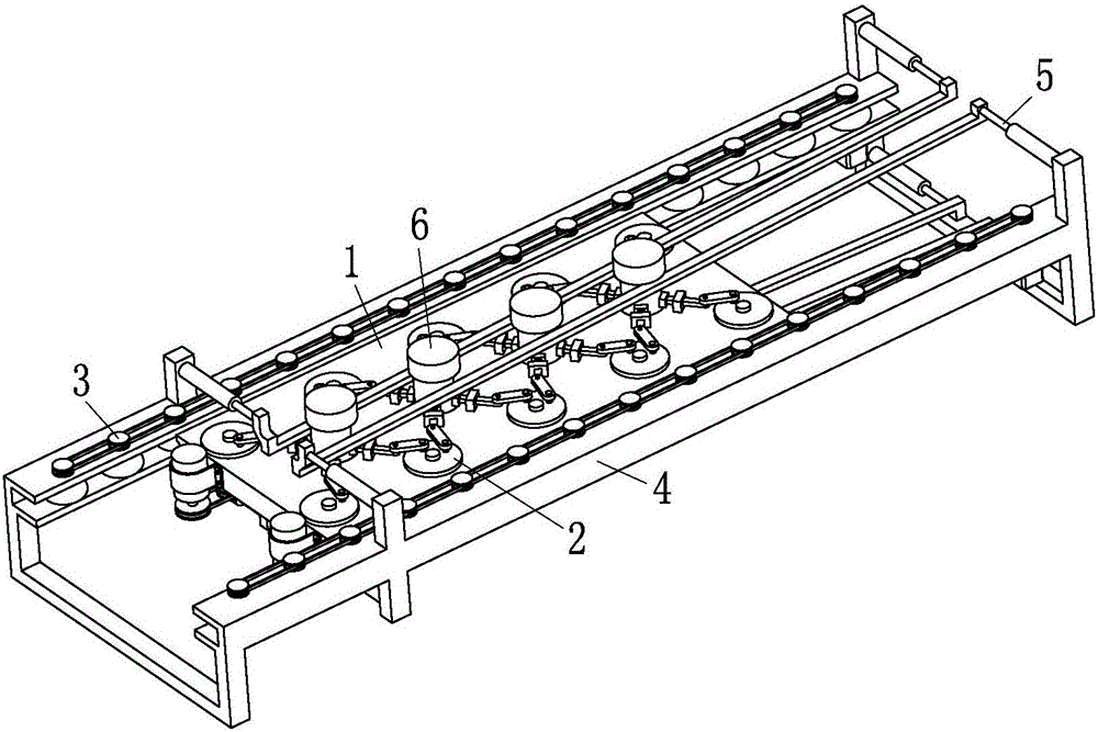
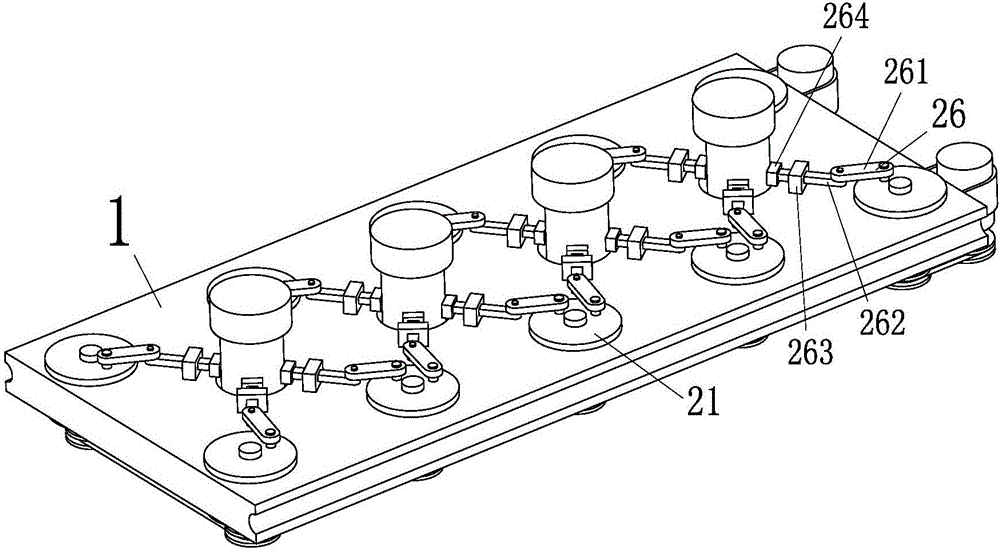
[0034] Such as figure 1 , figure 2 , image 3 , Figure 4 , Figure 5 with Image 6 As shown, a resistance automatic cap stripping assembly line according to the present invention includes a capacitive resistance plate 1 uniformly provided with round holes to accommodate the resistance 6, a clamp installed on the capacitance resistance plate 1 and clamping the resistance 6 with different diameters The resistance device 2, the resistance sending device 3 that pushes the capacitive resistance plate 1 to translate, the body 4 used to support the resistance sending device 3, and the puller installed on the body 4 for pulling out the resistance caps at the upper and lower ends of the resistance 6 Cap device 5;

[0035] At least four round holes are ...


PUM


Abstract

The invention relates to the field of resistors, in particular to an automatic resistor decapping production line. The automatic resistor decapping production line comprises a resistor holding plate, a resistor clamping device, a resistor conveying device and a cap pulling device. The resistor holding plate is uniformly provided with round holes to hold resistors, the resistor clamping device is mounted on the resistor holding plate and used for clamping the resistors different in diameter, the resistor conveying device is used for conveying the resistor holding plate to translate, and the cap pulling device is used for supporting a body of the resistor conveying device and mounted on the body to pull resistor caps at upper and lower ends of the resistors. Conveying chains can be arranged at both left and right ends of the resistor conveying device, the resistor clamping device comprises clamping ends in contact with resistor surfaces, and the cap pulling device comprises two pairs of horizontal cap pulling rods. The automatic resistor decapping production line can be used with external conveying chains to realize automatic resistor decapping operations, and high decapping efficiency is realized; in addition, automatic decapping of the resistors difference in diameter is realized, and structural simplicity, wide application range and high practicality are realized.

Description

technical field [0001] The invention relates to the field of resistors, in particular to an assembly line for automatic cap stripping of resistors. Background technique [0002] At present, in the production of resistors, it is necessary to use a capping machine to add caps to both ends of the resistor blank. Due to the failure of the capping machine or the discrepancy between the size of the resistor blank and the metal cap, it often results in the metal on one or both ends of the resistor blank. The cap is not installed firmly or falls off, resulting in defective products. One is discarding, the resistance body cannot be reused, resulting in a waste of resources and increasing the production cost of the enterprise; the other is manual removal of the cap, which is labor-intensive and inefficient. [0003] The Chinese patent has announced a resistance capping machine whose notification number is CN101950649B, which can automatically decap the resistance and realize the reus...

Claims


Application Information

Patent Timeline
Patent Type & Authority Applications(China)
IPC IPC(8): H01C17/00
CPCH01C17/00
Inventor 林飞飞
Owner 山东润蒙应急救援装备有限公司
Learn More