Table board used for automatic stacking of ultrahigh-voltage iron core

An ultra-high voltage, iron core technology, applied in the manufacture of inductors/transformers/magnets, workbenches, electrical components, etc., can solve problems that affect the appearance, size and performance of products, the working position cannot be switched at will, and the position is difficult to determine during operation. Achieve the effect of reducing professional skill requirements, improving operation efficiency and finished product quality, and convenient operation

Pending Publication Date: 2020-02-11
WUXI PUTIAN IRON CORE CO LTD
View PDF0 Cites 5 Cited by
  • Summary
  • Abstract
  • Description
  • Claims
  • Application Information

AI Technical Summary

Problems solved by technology

[0002] In the prior art, the core stacking platform is divided into two parts, one part is a lamination platform used for lamination alone, and the other part is a fixed turning mechanism combined with the lamination platform. The working position cannot be switched arbitrarily. It is time-consuming and labor-intensive to operate the turning mechanism to lift and combine it on the lamination platform. At the same time, the continuous application of external force to the iron core product by turning over by driving will affect the appearance, size and performance of the product
[0003] The existing stacking table, when placing the stacks according to the type of iron core, uses the crane or other tooling to pull the sliding beam to position the table. It is difficult to determine the position during operation, and it is time-consuming, laborious and unsafe.

Method used


Image

  • Table board used for automatic stacking of ultrahigh-voltage iron core
  • Table board used for automatic stacking of ultrahigh-voltage iron core

Examples


Embodiment Construction

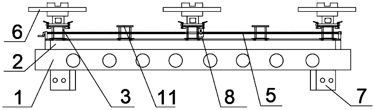
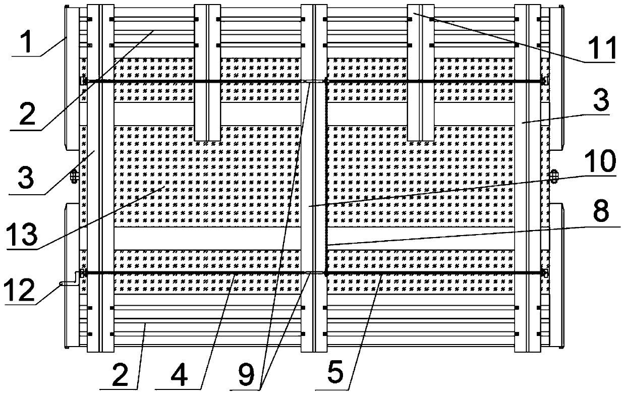
[0021] The specific implementation manner of the present invention will be described below in conjunction with the accompanying drawings.

[0022] Such as figure 1 and figure 2 As shown, the tabletop for automatic stacking of ultra-high voltage iron cores in this embodiment includes support feet 7 arranged in parallel at intervals, and a crossbeam 1 perpendicular to the stand 7 is installed on each of the two ends of the support feet 7, and a beam 1 is fixedly installed on the two crossbeams 1 respectively. One horizontal slide rail 2, a vertical fixed beam 10 is fixedly installed in the middle of the upper surface of the two horizontal slide rails 2 at the same time, the vertical fixed beam 10 is perpendicular to the horizontal slide rail 2, and there is one on both sides of the upper surface of the two horizontal slide rails 2 One vertical sliding long beam 3, two vertical sliding long beams 3 take the vertical fixed beam 10 as the center line, and slide toward each other ...


PUM


Abstract

The invention relates to a table board used for automatic stacking of an ultrahigh-voltage iron core. The table board comprises supporting legs which are arranged in parallel at intervals. Two ends ofeach supporting leg are provided with cross beams vertical to the supporting leg respectively. Transverse sliding rails are fixedly installed on the two cross beams respectively. Vertical fixed beamsare fixedly installed in the middle of upper surfaces of the two transverse sliding rails at the same time, the vertical fixed beam is vertical to each transverse sliding rail, two sides of the uppersurfaces of the two transverse sliding rails are provided with vertical sliding long beams, and the two vertical sliding long beams oppositely or reversely slide along the transverse sliding rails with the vertical fixed beam as a center line. In the invention, the vertical sliding long beams oppositely or reversely slide through two sets of transmission devices, and the table board is suitablefor iron core lamination operation of different sizes and types; through a door-frame-shaped structure formed by cross beam supporting legs, an air cushion vehicle can conveniently lift and convey thetable board inside and outside a workshop, and operation with an automatic hydraulic turnover mechanism of an automatic lamination stacking machine can be realized so as to achieve assembly line work; and work efficiency and finished product quality are greatly improved.

Description

technical field [0001] The invention relates to the technical field of multifunctional production equipment for stacking, assembling and flipping iron cores of power transformers, in particular to a table top for automatic stacking of ultra-high voltage iron cores. Background technique [0002] In the prior art, the core stacking platform is divided into two parts, one part is a lamination platform used for lamination alone, and the other part is a fixed turning mechanism combined with the lamination platform. The working position cannot be switched arbitrarily. It is time-consuming and labor-intensive to operate the turning mechanism to lift and combine it on the lamination platform. At the same time, the continuous application of external force to the iron core product by turning over by driving will affect the appearance, size and performance of the product. [0003] In the existing stacking table, when placing the laminations according to the type of iron core, the slidi...

Claims


Application Information

Patent Timeline
IPC IPC(8): H01F41/02B25H1/08B25H1/00
CPCB25H1/00B25H1/08H01F41/0233
Inventor 蔡子祥闫成亮魏龙张聪徐权勇
Owner WUXI PUTIAN IRON CORE CO LTD
Why Eureka
Try Eureka