A flexible touch display panel and a flexible touch display device

A touch display panel and flexible touch technology, applied in the direction of instruments, semiconductor devices, computing, etc., can solve the problems of affecting the touch accuracy, touch electrode signal display signal interference, and the distance between the touch electrode and the display unit is small, etc. Achieve the effects of improving bending resistance, ensuring touch stability, and increasing bending resistance

Active Publication Date: 2020-04-24
SHANGHAI TIANMA MICRO ELECTRONICS CO LTD
View PDF3 Cites 0 Cited by
  • Summary
  • Abstract
  • Description
  • Claims
  • Application Information

AI Technical Summary

Problems solved by technology

[0002] At present, in order to realize the touch function of the flexible display panel using Organic Light Emitting Diode (OLED, Organic Light Emitting Diode), it is usually necessary to attach a layer of touch module on the basis of the display panel, so that the flexible display panel cannot be thinned.
In order to realize the lightness and thinning of the touch-sensitive flexible display panel, the traditional module bonding technology is replaced by the integration technology. The current integration technology mainly integrates the touch electrode on the protective film layer, polarizer or glass For the thin film encapsulation layer, the above method reduces the thickness of the flexible display product to a certain extent, but since the touch electrodes are integrated inside the display panel, the distance between the touch electrodes and the display unit is very small, so the touch electrode signals will be affected by the display signal. Interference, thus affecting the touch accuracy

Method used


Image

  • A flexible touch display panel and a flexible touch display device
  • A flexible touch display panel and a flexible touch display device
  • A flexible touch display panel and a flexible touch display device

Examples


Embodiment Construction

[0023] The present invention will be further described in detail below in conjunction with the accompanying drawings and embodiments. It should be understood that the specific embodiments described here are only used to explain the present invention, but not to limit the present invention. In addition, it should be noted that, for the convenience of description, only some structures related to the present invention are shown in the drawings but not all structures. And for a clearer description, the same reference numerals are used between different drawings.

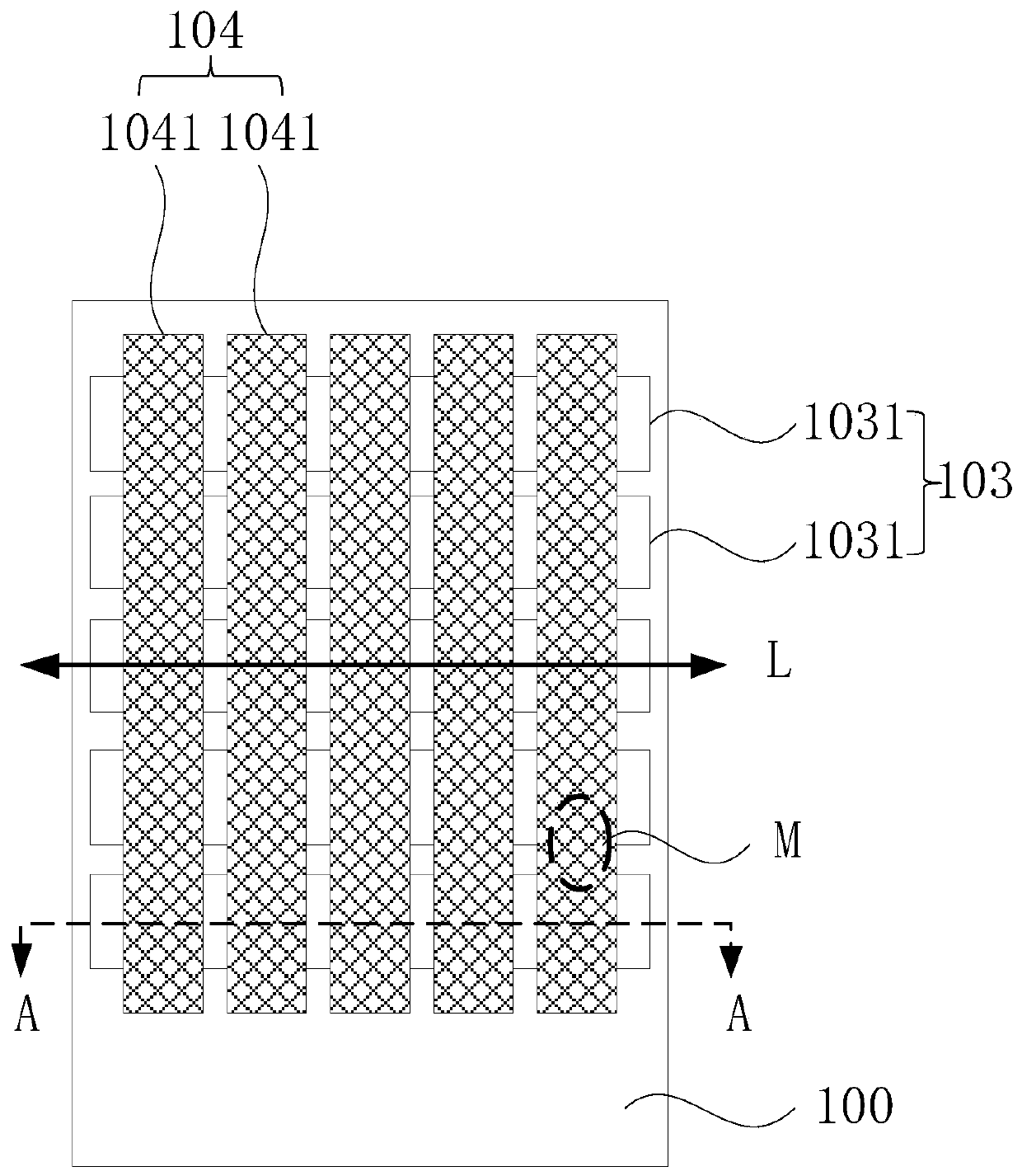
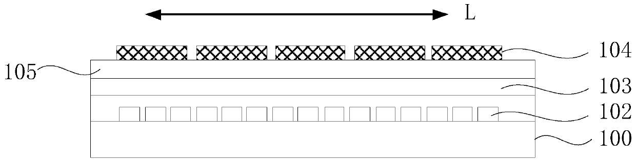
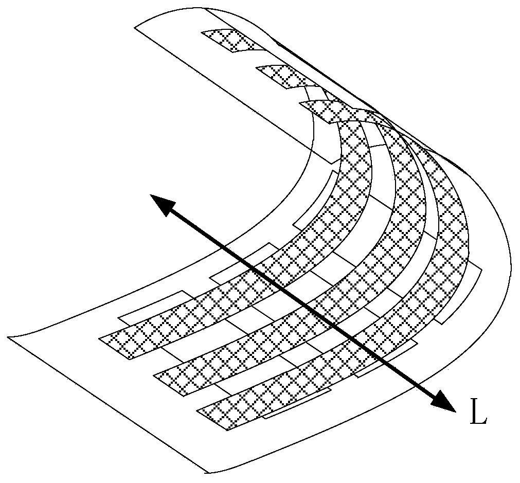
[0024] Figure 1a It is a schematic diagram of a flexible touch display panel provided by an embodiment of the present invention, Figure 1b is the sectional view of Fig. 1a along AA, Figure 1c A schematic diagram of the bending of the flexible touch display panel provided by the embodiment of the present invention along the bending axis, as shown in Figure 1a with Figure 1b As shown, the flexible touch display pan...


PUM


Abstract

The present invention provides a flexible touch display panel, comprising: a flexible substrate; a light-emitting unit layer arranged on the flexible substrate, the light-emitting unit layer includes a plurality of light-emitting units; a first touch electrode layer, a second touch electrode layer and a set The insulating layer between the first touch electrode layer and the second touch electrode layer, the first touch electrode layer includes a plurality of first touch electrodes insulated from each other, the first touch electrodes are striped along the display panel Extending in the direction of the bending axis; the second touch electrode layer includes a plurality of second touch electrodes insulated from each other. The second touch electrodes extend in a strip shape perpendicular to the direction of the bending axis and are arranged along the direction of the bending axis. The first touch electrode layer is a transparent conductive layer, and the second touch electrode layer is a metal grid. By setting the first touch electrode layer as a transparent conductive layer, the signal interference of the light emitting unit below to the touch electrodes can be shielded, thereby ensuring the touch stability of the flexible touch display panel.

Description

technical field [0001] The present invention relates to the display field, in particular to a flexible touch display panel and a flexible touch display device. Background technique [0002] At present, in order to realize the touch function, a flexible display panel using Organic Light Emitting Diode (OLED, Organic Light Emitting Diode) usually needs to attach a layer of touch module on the basis of the display panel, so that the flexible display panel cannot be thinned. In order to realize the lightness and thinning of the touch-sensitive flexible display panel, the traditional module bonding technology is replaced by the integration technology. The current integration technology mainly integrates the touch electrode on the protective film layer, polarizer or glass For the thin film encapsulation layer, the above method reduces the thickness of the flexible display product to a certain extent, but since the touch electrodes are integrated inside the display panel, the dista...

Claims


Application Information

Patent Timeline
Patent Type & Authority Patents(China)
IPC IPC(8): H01L27/32G06F3/041
CPCG06F3/041H10K59/40H10K59/131G06F3/0412G06F2203/04102G06F2203/04107G06F2203/04112G06F3/04166G06F3/0445
Inventor 姚绮君
Owner SHANGHAI TIANMA MICRO ELECTRONICS CO LTD
Why Eureka
Try Eureka