An automatic wire stripping machine

A technology of automatic wire stripping and wire stripping device, which is applied in the direction of line/collector parts, cable installation, disassembly/armored cable equipment, etc. Inability to peel off cleanly, etc., to achieve the effect of improving the efficiency of wire stripping, good wire stripping effect, and improving the effect of pressing

Active Publication Date: 2018-10-19
深圳市艾美迪电子科技有限公司
View PDF5 Cites 2 Cited by
  • Summary
  • Abstract
  • Description
  • Claims
  • Application Information

AI Technical Summary

Problems solved by technology

[0003] Most of the existing wire stripping is manually operated, and the plastic at the end of the cable is peeled off manually through the wire stripper. However, the manual operation is inefficient and cannot be adapted to large-scale production. Therefore, some wire stripping machines have appeared, but Wire stripping requires two steps, that is, clamping and pulling. Existing wire stripping machines usually use fixed wire controls with different apertures to fix the cable terminals, which is easy to cause falling off. In addition, the rubber at the end of the cable is due to It is always suspended in the air, so it cannot be peeled off cleanly, and manual operation is required, which is very troublesome

Method used


Image

  • An automatic wire stripping machine
  • An automatic wire stripping machine
  • An automatic wire stripping machine

Examples


Embodiment Construction

[0029] In order to enable those skilled in the art to better understand the technical solution of the present invention, the present invention will be described in detail below in conjunction with the accompanying drawings. The description in this part is only exemplary and explanatory, and should not have any limiting effect on the protection scope of the present invention. .

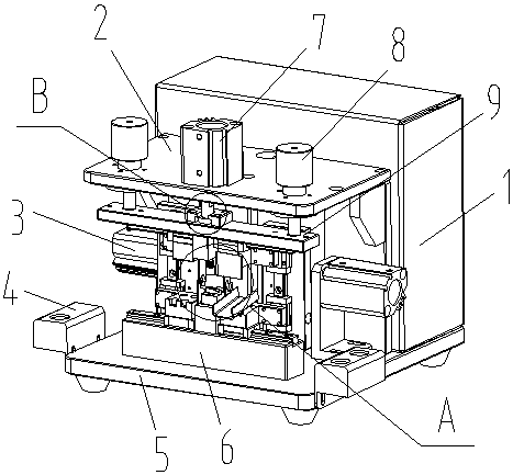
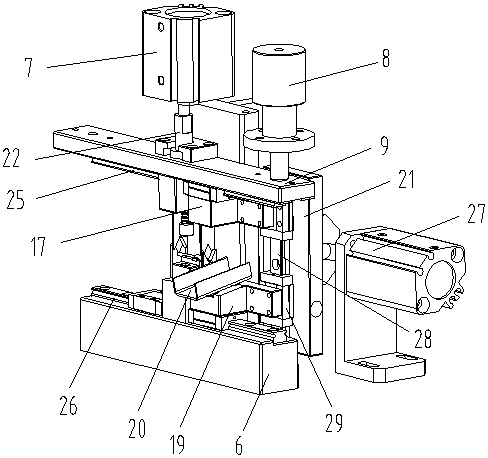
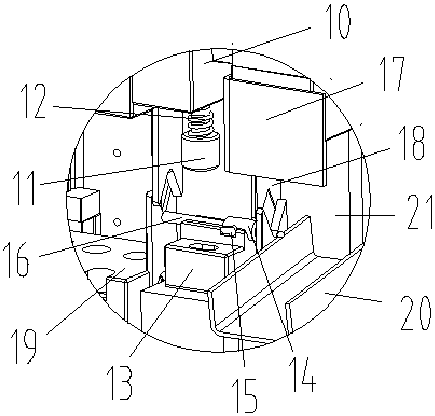
[0030] Such as Figure 1-Figure 4 As shown, the specific structure of the present invention is: an automatic wire stripping machine, which includes a support frame 5, the support frame 5 is fixed by the mounting seat 4, and the rear portion of the support frame 5 is provided with a power distribution control The box 1 is provided with a mounting block 6 at the front, and the mounting block 6 is provided with a loading block 13 matched with the cable 16, and the power distribution control box 1 is provided with a top plate 2, and the top plate 2 The middle part is provided with a pressing device that c...


PUM


Abstract

The invention relates to an automatic wire-stripping machine comprising a support frame fixed by a mounting block. A power distribution control box is arranged at the back side of the support frame; the mounting block is arranged at the front side; and a loading block cooperating with a cable is arranged at the mounting block. A top plate is arranged at the power distribution control box; a compressing device cooperating with the loading block is arranged in the middle of the top plate; clamping cylinders are arranged at the two sides of the top plate and are connected with a lifting block; and wire stripping devices are arranged below the lifting block. The wire stripping devices include upper moving blocks and lower moving blocks; the upper moving blocks cooperate with an upper sliding rail arranged below the lifting plate; the lower moving blocks cooperate with a lower sliding rail arranged below the mounting block; and clamp blocks are arranged at the upper moving blocks and the lower moving blocks; and the upper moving blocks and the lower moving blocks are connected to a synchronous pulling device. According to the automatic wire-stripping machine, because the clamp blocks cooperating with the cable are arranged at an upper direction and a lower direction of the end portion of the cable, a support effect is realized during the pulling and wire stripping process; the stripping is done completely and the wire stripping effect is good; the operation becomes simple; and the wire stripping efficiency can be improved.

Description

technical field [0001] The invention relates to the field of cable application equipment, in particular to an automatic wire stripping machine. Background technique [0002] With the development and promotion of electric power, the use of cables is becoming more and more extensive. Basically, cables are used in all walks of life. The end of the cable is stripped to expose the copper core. This process is called the stripping process. [0003] Most of the existing wire stripping is manually operated, and the plastic at the end of the cable is peeled off manually through the wire stripper. However, the manual operation is inefficient and cannot be adapted to large-scale production. Therefore, some wire stripping machines have appeared, but Wire stripping requires two steps, that is, clamping and pulling. Existing wire stripping machines usually use fixed wire controls with different apertures to fix the cable terminals, which is easy to cause falling off. In addition, the rub...

Claims


Application Information

Patent Timeline
Patent Type & Authority Patents(China)
IPC IPC(8): H01R43/28H02G1/12
CPCH01R43/28H02G1/1248
Inventor 不公告发明人
Owner 深圳市艾美迪电子科技有限公司
Why Eureka
Try Eureka