

Landscaping lawn pest breeding prevention pesticide spraying device
A technology for landscaping and pesticide spraying, which is applied to devices for application, capture or killing of insects, animal husbandry, etc., can solve the problems of difficult adjustment of the height of the nozzle, heavy workload of workers, easy precipitation of pesticides, etc., and achieves a small workload of workers. , long service life and high hardness
- Summary
- Abstract
- Description
- Claims
- Application Information
AI Technical Summary
Problems solved by technology
Method used
Image

Examples
Embodiment 1
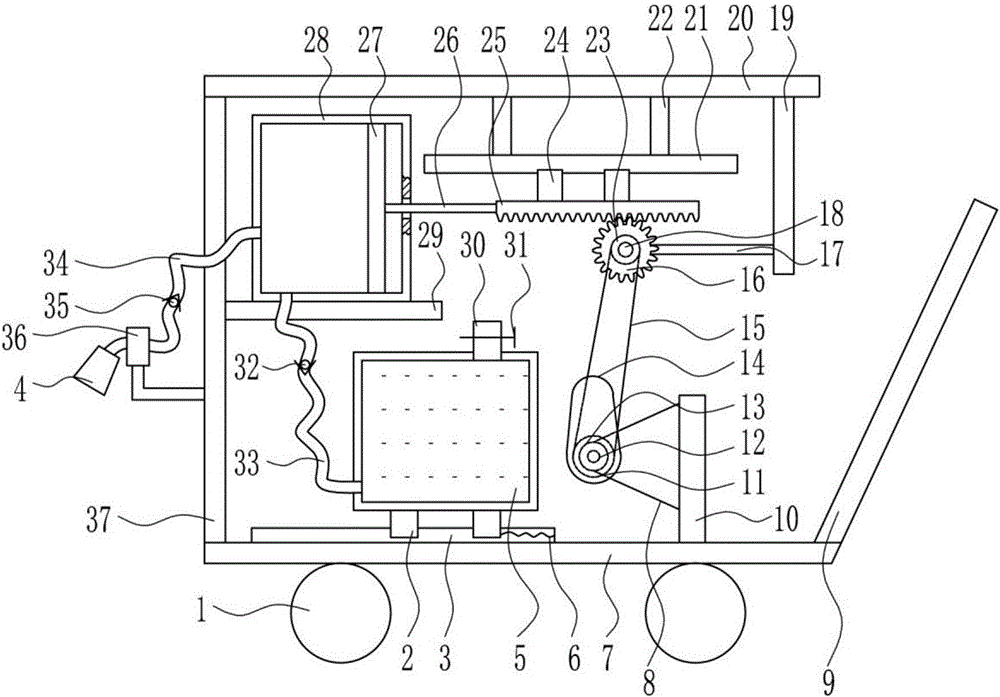
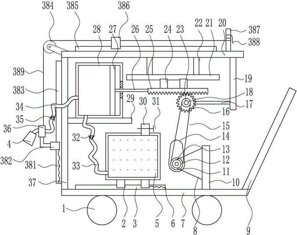
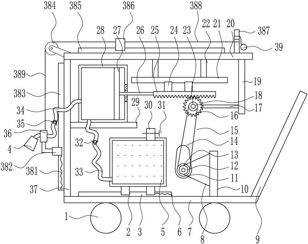
[0028] A kind of pesticide spraying equipment for landscaping to prevent the reproduction of lawn diseases and insect pests, such as Figure 1-3 As shown, it includes a wheel 1, a first slider 2, a first slide rail 3, a nozzle 4, a box body 5, a first spring 6, a bottom plate 7, a mounting seat 8, a push handle 9, a mounting plate 10, a large pulley 11, Rotating shaft 12, bearing seat 13, cam 14, flat belt 15, gear 16, support 17, motor 18, first fixed plate 19, top plate 20, second slide rail 21, support frame 22, small pulley 23, second slide block 24. Rack 25, connecting rod 26, piston 27, cylinder 28, second fixed plate 29, liquid inlet pipe 30, valve 31, first one-way valve 32, first hose 33, second hose 34, The second one-way valve 35, the fixed sleeve 36 and the left frame 37, the left frame 37 is welded on the left end of the bottom plate 7 top, the fixed sleeve 36 is welded on the lower left side of the left frame 37, and the second fixed plate 29 is welded on the upp...
PUM
 Abstract
Description
Claims
Application Information