C-arm system rotational angle calibration device and C-arm system calibration method

A technology of rotation angle and calibration device, which is used in medical science, instruments for radiological diagnosis, diagnosis, etc., and can solve the problem of inability to calibrate the rotation angle of the C-arm system.

Active Publication Date: 2017-06-13
SHENZHEN INST OF ADVANCED TECH
View PDF9 Cites 11 Cited by
  • Summary
  • Abstract
  • Description
  • Claims
  • Application Information

AI Technical Summary

Problems solved by technology

[0005] The object of the present invention is to provide a C-arm system rotation angle calibration device and a method for calibrating the C-arm system by using the C-arm

Method used


Image

  • C-arm system rotational angle calibration device and C-arm system calibration method

Examples


Embodiment 1

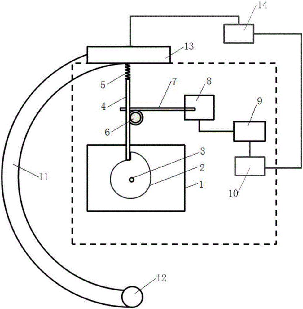
[0032] Such as figure 1 As shown, the present invention provides a C-arm system rotation angle calibration device, including: a motion conversion assembly, a displacement sensor 8 , a data transmitter 9 and a processor 10 .

[0033] The motion conversion assembly includes a base 1 , a cam 2 , a longitudinal rack 4 , a spring 5 , a transmission gear set 6 and a transverse rack 7 . The cam 2 is fixed on the base 1 through the fixed shaft 3, the fixed shaft 3 is located on the geometric center of the cam 2, and is perpendicular to the base 1, and the position of the cam 2 on the base 1 can be adjusted as required. One end of the longitudinal rack 4 is in contact with the contour of the cam 2 , and this end can move along the contour of the cam 2 , and the other end of the longitudinal rack 4 is connected with a spring 5 . The transverse rack 7 is in transmission connection with the longitudinal rack 4 through the transmission gear set 6 . The displacement sensor 8 is connected ...

Embodiment 2

[0049] For the sake of brevity, only the differences between the second embodiment and the first embodiment will be described. The difference is that the motion conversion component can also be other mechanical structures that can convert rotary motion into linear motion, such as a crank-slider mechanism Or crank linkage mechanism etc.


PUM


Abstract

The invention relates to the technical field of CT (computed tomography) system parameter calibration, in particular to a C-arm system rotational angle calibration device and a C-arm system calibration method; the C-arm system rotational angle calibration device comprises a motion conversion component, a displacement sensor, a data transmitter and a processor, the motion conversion component is arranged to connect with a C-arm and convert rotational motion of the C-arm into linear motion, the displacement sensor is connected with the motion conversion component and is arranged to acquire a displacement signal of the motion conversion component and transmit the displacement signal to the data transmitter connected with the displacement sensor, and the processor is connected with the data transmitter and is arranged to receive and analyze the displacement signal transmitted by the data transmitter. The C-arm system rotational angle calibration device is simple to operate, good in operational stability and reliability, and free of X-ray exposure in use, so that the radiation risk can be lowered.

Description

technical field [0001] The invention relates to the technical field of CT system parameter calibration, in particular to a C-arm system rotation angle calibration device and a C-arm system calibration method. Background technique [0002] The medical diagnostic equipment based on X-ray radiation is called C-arm. C-arm equipment is more and more widely used in the medical field. The C-arm can move along the guide rail around the part of the patient to be examined or treated, which can The purpose of comprehensive examination of patients who are inconvenient to move or move. An X-ray device consisting of an X-ray light source at one end of a C-arm, an X-ray detector or an image intensifier at the opposite end of the C-arm, and other mechanical structures is more and more widely used as a diagnostic device. [0003] In X-ray three-dimensional image reconstruction, the quality of the reconstructed image will be affected whether the running trajectory of the X-ray light source a...

Claims


Application Information

Patent Timeline
IPC IPC(8): A61B6/00
CPCA61B6/582
Inventor 陈垦王澄秦文健熊璟谢耀钦
Owner SHENZHEN INST OF ADVANCED TECH
Why Eureka
Try Eureka