Rehabilitative apparatus for lumbar disc herniation
A technology of lumbar intervertebral disc herniation and right support plate, which is applied in the field of medical devices, can solve the problems of heavy spinal load, aggravated pain of patients, aggravated symptoms, etc., and achieves the effect of smooth operation.
- Summary
- Abstract
- Description
- Claims
- Application Information
AI Technical Summary
Problems solved by technology
Method used
Image
Examples
Embodiment 1
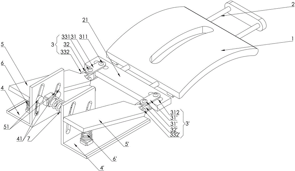
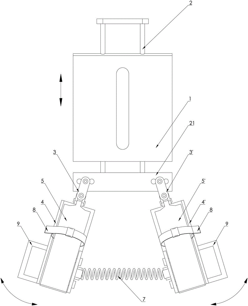
[0030] A lumbar intervertebral disc herniation rehabilitation device, comprising a top pressure plate 1, the top surface of the top pressure plate 1 is in an upward convex arc shape, the lower edge of the top pressure plate 1 is installed on the slide rails 2 arranged in the front and back direction, and the rear side of the slide rail seat 21 is provided with a left 1. Right movable joint (3,3 '), the front joint part (31,31 ') front end of left and right movable joint (3,3 ') is detachable with the gear on the rear side of slide rail seat 21 through gear column 311 The position holes 312 are fixed to each other, and the position holes 312 are symmetrically arranged left and right, and the left and right pressure plates (5, 5') connected to the left and right movable joints (3, 3') are mutually arranged with a distance. By inserting the gear column 311 into different gear holes 312, the width between the left and right movable joints (3, 3') can be changed;
[0031] In this e...
Embodiment 2
[0037] Embodiment 2 is based on Embodiment 1 and improves and perfects the composition, and its main structure is the same as Embodiment 1. Further improvements are as follows: figure 2 As shown, the horizontal pulley block 35 is arranged symmetrically on the lower edge of the left and right support plates (4, 4'), and the longitudinal pulley block 15 is set on the lower edge of the top pressure plate 1, under the control of the normal compression spring, the left and right pressure plates (5, 5') and The left and right support plates (4, 4') are kept between the minimum and maximum relative displacement distances. In this embodiment, after the compression springs are installed, the left and right pressure plates (5, 5') correspond to the left and right Keep the angle between the right support plate (4,4') of 20°~40°, and the distance between the left and right pressure plate (5,5') and the left and right support plate (4,4') is controlled within the range of 20-30cm , and un...
Embodiment 3
[0042] Embodiment 3 is an improved structure based on Embodiment 1 and 2. It is characterized in that the arc-shaped protrusion of the top pressure plate 1 has the same arc as the natural curvature of the back, and the left and right support plates (4, 4') are provided with Holding the handle 9, the left and right pressure plates (5,5') are provided with elastic bands 8, and the left and right compression springs (6,6') are detachably connected to the bottom of the left and right pressure plates (5,5') through snap bolts , the corresponding engaging holes on the top of the left and right support plates (4,4') are connected to each other; similarly, the central spring is detachably connected to the locking pins of the left and right baffles (41,41') through the engaging bolts. Holes are connected to each other. Through this design, the user can hold the handle 9 during the rehabilitation process, which is convenient for the whole body to exert force;
[0043] In addition to ad...
PUM
 Abstract
Description
Claims
Application Information
 - R&D
- Intellectual Property
- Life Sciences
- Materials
- Tech Scout
- Unparalleled Data Quality
- Higher Quality Content
- 60% Fewer Hallucinations
Browse by: Latest US Patents, China's latest patents, Technical Efficacy Thesaurus, Application Domain, Technology Topic, Popular Technical Reports.
© 2025 PatSnap. All rights reserved.Legal|Privacy policy|Modern Slavery Act Transparency Statement|Sitemap|About US| Contact US: help@patsnap.com


